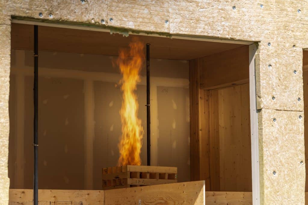
Welcome to the new CWC Digital Resource Hub (BETA)

Building with Wood

Explore our diverse range of topics related to building with wood.

54 results found...
Sort By Dropdown Icon

In the National Building Code of Canada (NBC) “fire-resistance rating” is defined in part as: “the time in minutes or hours that a material or assembly of materials will withstand the passage of flame and the transmission of heat when exposed to fire under specified conditions of test and performance criteria…”

The fire-resistance rating is the time, in minutes or hours, that a material or assembly of materials will withstand the passage of flame and the transmission of heat when exposed to fire under specified conditions of test and performance criteria, or as determined by extension or interpretation of information derived therefrom as prescribed in the NBC.

The test and acceptance criteria referred to in the NBC are contained in a standard fire test method, CAN/ULC-S101, published by ULC Standards.

Underside of floor showing joists. The fire-resistance rating is required from the underside of the assembly only.

Horizontal assemblies such as floors, ceilings and roofs are tested for fire exposure from the underside only. This is because a fire in the compartment below presents the most severe threat. For this reason, the fire-resistance rating is required from the underside of the assembly only. The fire-resistance rating of the tested assembly will indicate, as part of design limitations, the restraint conditions of the test. When selecting a fire-resistance rating, it is important to ensure that the restraint conditions of the test are the same as the construction in the field. Wood-frame assemblies are normally tested with no end restraint to correspond with normal construction practice.

Early stages of framing with floor joists and loadbearing beam showing.

Partitions or interior walls required to have a fire-resistance rating must be rated equally from each side, since a fire could develop on either side of the fire separation. They are normally designed symmetrically. If they are not symmetrical, the fire-resistance rating of the assembly is determined based on testing from the weakest side. For a loadbearing wall, the test requires the maximum load permitted by design standards be superimposed on the assembly. Most wood-stud wall assemblies are tested and listed as loadbearing. This allows them to be used in both loadbearing and non-loadbearing applications.

Listings for loadbearing wood stud walls can be used for non-loadbearing cases since the same studs are used in both applications. Loading during the test is critical as it affects the capacity of the wall assembly to remain in place and serve its purpose in preventing fire spread. The strength loss in studs resulting from elevated temperatures or actual burning of structural elements causes deflection. This deflection affects the capacity of the protective wall membranes (gypsum board) to remain in place and contain the fire. The fire-resistance rating of loadbearing wall assemblies is typically lower than that of a similarly designed non-loadbearing assembly.

Exterior walls only require rating for fire exposure from within a building. This is because fire exposure from the exterior of a building is not likely to be as severe as that from a fire in an interior room or compartment. Because this rating is required from the inside only, exterior wall assemblies do not have to be symmetrical.

The NBC permits the authority having jurisdiction to accept results of fire tests performed according to other standards. Since test methods have changed little over the years, results based on earlier or more recent editions of the CAN/ULC-S101 standard are often comparable. The primary US fire-resistance standard, ASTM E119, is very similar to the CAN/ULC-S101 standard. Both use the same time-temperature curve and the same performance criteria. Fire-resistance ratings developed in accordance with ASTM E119 are usually acceptable to Canadian officials. Whether an authority having jurisdiction accepts the results of tests based on these standards depends primarily on the official’s familiarity with them.

Testing laboratories and manufacturers also publish information on proprietary listings of assemblies which describe the materials used and assembly methods. A multitude of fire-resistance tests have been conducted over the last 70 years by North American laboratories. Results are available as design listings or reports through:

In addition, manufacturers of construction products publish results of fire-resistance tests on assemblies incorporating their proprietary products (for example, the Gypsum Association’s GA-600 Fire Resistance Design Manual).

The NBC contains generic fire-resistance rating information for wood assemblies and members. This includes fire and sound resistance tables describing various wall and floor assemblies of generic building materials that assign specific fire-resistance ratings to the assemblies. Over the last two decades a number of large research projects were conducted at the National Research Council of Canada (NRC) on light-frame wall and floor assemblies, looking at both fire resistance and sound transmission. As a result, the NBC has hundreds of different wall and floor assemblies with assigned fire-resistance ratings and sound transmission ratings. These results are published in the NBC Table A-9.10.3.1.A. Fire and Sound Resistance of Walls and NBC Table A-9.10.3.1.B Fire and Sound Resistance of Floors, Ceilings and Roofs. Not all assemblies described were actually tested. The fire-resistance ratings for some assembles were extrapolated from fire tests done on similar wall assemblies. The listings are useful because they offer off-the-shelf solutions to designers. They can, however, restrict innovation because designers use assemblies which have already been tested rather than pay to have new assemblies evaluated. Listed assemblies must be used with the same materials and installation methods as those tested.

The previous section on fire-resistance ratings deals with the determination of fire-resistance ratings from standard tests. Alternative methods for determining fire-resistance ratings are permitted as well. The alternative methods of determining fire-resistance ratings are contained in the NBC, Division B, Appendix D, Fire Performance Ratings. These alternative calculation methods can replace expensive proprietary fire tests. In some cases, these allow less stringent installation and design requirements such as alternate fastener details for gypsum board and the allowance of openings in ceiling membranes for ventilation systems. Section D-2 in NBC, Division B, Appendix D includes methods of assigning fire-resistance ratings to:

  • wood-framed walls, floors and roofs in Appendix D-2.3. (Component Additive Method);
  • solid wood walls, floors and roofs in Appendix D-2.4.; and,
  • glue-laminated timber beams and columns in Appendix D-2.11.

The most practical alternative calculation method includes procedures for calculating the fire-resistance rating of lightweight wood-frame wall, floor and roof assemblies based on generic descriptions of materials. This component additive method (CAM) can be used when it is clear that the fire-resistance rating of an assembly depends strictly on the specification and arrangement of materials for which nationally recognized standards exist. The assemblies must conform to all requirements in NBCC, Division B, Appendix D-2.3. Wood and Steel Framed Walls, Floors and Roofs.

While the information currently contained in Appendix D-2.4. addresses more historic construction techniques, there has been some resurgence in the use of such assemblies, and the information can be particularly useful when repurposing historic buildings.

NBC, Division B, Appendix D also includes empirical equations for calculating the fire-resistance rating of glue-laminated (glulam) timber beams and columns, in Appendix D-2.11. These equations were developed from theoretical predictions and validated by test results. Large wood members have an inherent fire resistance because:

  • the slow burning rate of large timbers, approximately 0.6 mm/minute under standard fire test conditions; and,
  • the insulating effects of the char layer, which protects the unburned portion on the wood.

These factors result in unprotected members that can stay in place for a considerable time when exposed to fire. The NBC recognizes this characteristic and allows unprotected wood members, including floor and roof decks, that meet the minimum sizes for heavy timber construction to be used both where a 45-minute fire-resistance rating is required and in many noncombustible buildings. The calculation method in Appendix D determines a fire-resistance rating for glulam beams and columns based on exposure to fire from three or four sides.

The formula for columns or beams which may be exposed on three sides applies only when the unexposed face is the smaller side of a column; no experimental data exists to verify the formula when a larger side is unexposed. If a column is recessed into a wall or a beam into a floor, the full dimensions of the structural member are used in the formula for exposure to fire on three sides. Comparisons of the calculated fire-resistance ratings with experimental results show the calculated values are very often conservative. A designer may determine the factored resistance for a beam or column by referring to CSA O86 Canadian Wood Council’s Wood Design Manual.

As well, the CSA O86 standard includes an informative Annex B that provides a method to calculate fire-resistance ratings for large cross-section wood elements, such as beams and columns of glued-laminated timber, solid-sawn heavy timber and structural composite lumber.

Further information on the calculation of fire resistance of heavy timber members is available in the American Wood Council’s publication Technical Report 10: Calculating the Fire Resistance of Exposed Wood Members (TR10).


For further information, refer to the following resources:

Wood Design Manual (Canadian Wood Council)

Fire Safety Design in Buildings (Canadian Wood Council)

National Building Code of Canada

National Fire Code of Canada

CSA O86, Engineering design in wood

CAN/ULC-S101 Standard Method of Fire Endurance Tests of Building Construction and Materials

ASTM E119 Standard Test Methods for Fire Tests of Building Construction and Materials

American Wood Council

Sultan, M.A., Séguin, Y.P., and Leroux, P.; “IRC-IR-764: Results of Fire Resistance Tests on Full-Scale Floor Assemblies”, Institute for Research in Construction, National Research Council Canada, May 1998.

Sultan, M. A., Latour, J. C., Leroux, P., Monette, R. C., Séguin, Y. P., and Henrie, J. P.; “RR-184: Results of Fire Resistance Tests on Full-Scale Floor Assemblies – Phase II”, Institute for Research in Construction, National Research Council Canada, March 2005.

Sultan, M.A., and Lougheed, G.D.; “IRC-IR-833: Results of Fire Resistance Tests on Full-Scale Gypsum Board Wall Assemblies”, Institute for Research in Construction, National Research Council Canada, August 2002

Heavy timber construction

Performance of Adhesives in Finger-joined Lumber in Fire-resistance-rated Wall Assemblies

Fire Separations & Fire-resistance Ratings


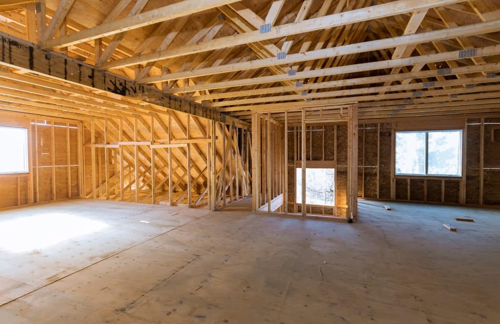
The vulnerability of any building in a fire situation is higher during the construction phase when compared to the susceptibility of the building after it has been completed and occupied. This is because the risks and hazards found on a construction site differ both in nature and potential impact from those in a completed building. And, these risks and hazards are occurring at a time when the fire prevention and protection elements that are designed to be part of the completed building are not yet in place.

For these reasons, construction site fire safety includes some unique challenges. However, an understanding of the hazards and their potential risks is the first step towards fire prevention and mitigation.

It is important to comply with applicable regulations related to fire safety planning during construction, and cooperation between all stakeholders in establishing and implementing a plan goes a long way in reducing the potential risk and impacts of a fire on any construction sites. In addition to province-wide regulations, local governments and municipalities can also have specific laws, regulations or requirements that must be followed. The local fire department can be a resource in directing you to these additional regulations or requirements.

Construction site safety has the potential to impact productivity and profitability at any phase of the project. Given that provincial or municipal regulations provide the minimum requirements for construction site fire safety, consideration should also be given to the specific characteristics, objectives and goals of the project, which could provide incentives to exceed the regulated standards for construction site fire safety. It can be prudent to assess and implement various ‘best practices’, based on the specific needs of your site, which can provide an additional level of protection and build a culture of fire safety.

Most construction site fires can be prevented with knowledge, planning and diligence; and, the impact of those fires that might occur can be significantly lessened. Understanding and addressing both the general and specific hazards and risks of a particular construction site requires education and training, as well as preparedness and continued vigilance.


For further information, refer to the following resources:

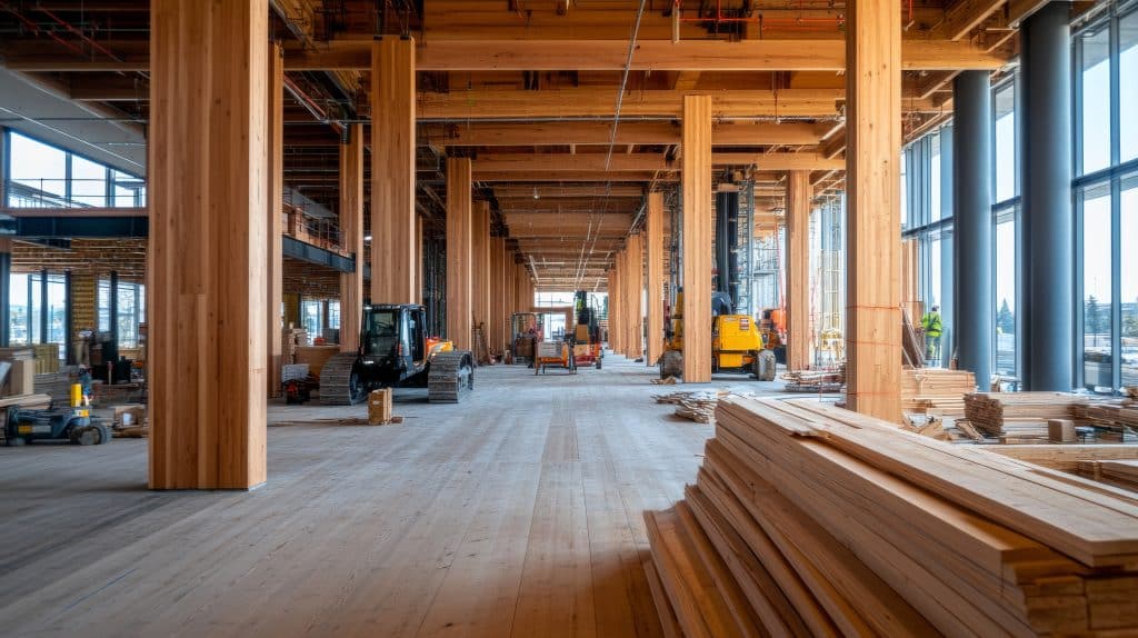
A structure must be designed to resist all the loads expected to act on the structure during its service life. Under the effects of the expected applied loads, the structure must remain intact and perform satisfactorily. In addition, a structure must not require an inordinate amount of resources to construct. Thus, the design of a structure is a balance of necessary reliability and reasonable economy.

Wood products are frequently used to provide the principal means of structural support for buildings. Economy and soundness of construction can be achieved by using wood products as members for structural applications such as joists, wall studs, rafters, beams, girders, and trusses. In addition, wood sheathing and decking products perform both a structural role by transferring wind, snow, occupant and content loads to the main structural members, as well as the function of building enclosure. Wood can be used in many structural forms such as light-frame housing and small buildings that utilize repetitive small dimension members or within larger and heavier structural framing systems, such as mass timber construction, which is often utilized for commercial, institutional or industrial projects. The engineered design of wood structural components and systems is based on the CSA O86 standard.

During the 1980s, the design of wood structures in Canada, as directed by the National Building Code of Canada (NBC) and CSA O86, changed from working stress design (WSD) to limit states design (LSD), making the structural design approach for wood similar to those of other major building materials.

All structural design approaches require the following for both strength and serviceability:

Member resistance = Effects of design loads

Using the LSD method, the structure and its individual components are characterized by their resistance to the effects of the applied loads. The NBC applies factors of safety to both the resistance side and the load side of the design equation:

Factored resistance = Factored load effect

The factored resistance is the product of a resistance factor (f) and the nominal resistance (specified strength), both of which are provided in CSA O86 for wood materials and connections. The resistance factor takes into account the variability of dimensions and material properties, workmanship, type of failure, and uncertainty in the prediction of resistance. The factored load effect is calculated in accordance with the NBC by multiplying the actual loads on the structure (specified loads) by load factors that account for the variability of the load.

No two samples of wood or any other material are exactly the same strength. In any manufacturing process, it is necessary to recognize that each manufactured piece will be unique. Loads, such as snow and wind, are also variable. Therefore, structural design must recognize that loads and resistances are really groups of data rather than single values. Like any group of data, there are statistical attributes such as mean, standard deviation, and coefficient of variation. The goal of design is to find a reasonable balance between reliability and factors such as economy and practicality.

The reliability of a structure depends on a variety of factors that can be categorized as follows:

  • external influences such as loads and temperature change;
  • modelling and analysis of the structure, code interpretations, design assumptions and other judgements which make up the design process;
  • strength and consistency of materials used in construction; and
  • quality of the construction process.

The LSD approach is to provide adequate resistance to certain limit states, namely strength and serviceability. Strength limit states refer to the maximum load-carrying capacity of the structure. Serviceability limit states are those that restrict the normal use and occupancy of the structure such as excessive deflection or vibration. A structure is considered to have failed or to be unfit for use when it reaches a limit state, beyond which its performance or use is impaired.

The limit states for wood design are classified into the following two categories:

  • Ultimate limit states (ULS) are concerned with life safety and correspond to the maximum load-carrying capacity and include such failures as loss of equilibrium, loss of load-carrying capacity, instability and fracture; and
  • Serviceability limit states (SLS) concern restrictions on the normal use of a structure.

Examples of SLS include deflection, vibration and localized damage.

Due to the unique natural properties of wood such as the presence of knots, wane or slope of grain, the design approach for wood requires the use of modification factors specific to the structural behaviour. These modification factors are used to adjust the specified strengths provided in CSA O86 in order to account for material characteristics specific to wood. Common modification factors used in structural wood design include duration of load effects, system effects related to repetitive members acting together, wet or dry service condition factors, effects of member size on strength, and influence of chemicals and pressure treatment

Wood building systems have high strength-to-weight ratios and light-frame wood construction contains many small connectors, most commonly nails, which provide significant ductility and capacity when resisting lateral loads, such as earthquake and wind.

Light-frame shearwalls and diaphragms are a very common and practical lateral bracing solution for wood buildings. Typically, the wood sheathing, most commonly plywood or oriented strand board (OSB), that is specified to resist the gravity loading can also act as the lateral force resisting system. This means that the sheathing serves a number of purposes including distributing loads to the floor or roof joists, bracing beams and studs from buckling out of plane, and providing the lateral resistance to wind and earthquake loads. Other lateral load resisting systems that are used in wood buildings include rigid frames or portal frames, knee bracing and cross-bracing.

A table of typical spans is presented below to aid the designer in selecting an appropriate wood structural system.

Estimated span capabilities of wood members in structural design for decking joists, beams, trusses and arches. 


For further information, refer to the following resources:

Introduction to Wood Design (Canadian Wood Council)

Wood Design Manual (Canadian Wood Council)

CSA O86 Engineering design in wood

National Building Code of Canada

www.woodworks-software.com

For many years, the design values of Canadian dimension lumber were determined by testing small clear samples. Although this approach had worked well in the past, there were some indications that it did not always provide an accurate reflection of how a full-sized member would behave in service.

Beginning in the 1970s, new data was gathered on full-size graded lumber, known as in-grade testing. In the early 1980s, the Canadian lumber industry conducted a major research program through the Canadian Wood Council Lumber Properties Program for bending, tension and compression parallel to grain strength properties of 38 mm thick (nominal 2 in) dimension lumber of all commercially important Canadian species groups. The Lumber Properties Program was conducted as a cooperative project with the US industry with the goal of verifying lumber grading correlation from mill to mill, from region to region, and between Canada and the United States.

The in-grade testing program involved testing thousands of pieces of dimension lumber to destruction in order to determine their in-service characteristics. It was agreed that this testing program should simulate, as closely as possible, the structural end use conditions to which the lumber would be subjected to.

After the test samples were conditioned to approximately 15 percent moisture content, they were tested under short- and long-term loading in accordance with ASTM D4761. Lumber samples in three sizes; 38 x 89 mm, 38 x 184 mm and 38 x 235 mm (2 x 4 in, 2 x 8 in, and 2 x 10 in), were selected across the Canadian growing regions for the three largest-volume commercial species groups; Spruce-Pine-Fir (S-P-F), Douglas Fir-Larch (D.Fir-L) and Hem-Fir. Select Structural, No.1, No.2, No.3, as well as light framing grades, were sampled in flexure. Select Structural, No.1 and No.2 grades were evaluated in tension and compression parallel to grain. Several lesser-volume species were also evaluated at lower sampling intensities.

The in-grade testing resulted in new relationships between species, sizes and grades. The dimension lumber database of results was examined to establish trends in bending, tension and compression parallel to grain property relationships as affected by member size and grade. These studies provided a basis for extending the results to the full range of dimension lumber grades and member sizes described in CSA O86. In Canada, both the CSA O86 and the National Building Code of Canada (NBC) have adopted the results from the Lumber Properties Program. The data has also been used to update the design values in the United States.

The scientific data resulting from the Lumber Properties Program demonstrated:

  • close correlation in the strength properties of visually graded No.1 and No.2 dimension lumber;
  • good correlation in the application of grading rules from mill to mill and from region to region; and
  • a decrease in relative strength as size increases (i.e. size effect) – for example the unit bending strength for a 38 × 89 mm (2 x 4 in) member is greater than for a 38 × 114 mm (2 x 6 in) member.

Following the testing program, the consensus-based ASTM D1990 standard was developed and published. Data for bending, tension parallel to grain, compression parallel to grain, and modulus of elasticity continue to be analyzed in accordance with this Standard.

Unlike visually graded lumber where the anticipated strength properties are determined from assessing a piece on the basis of visual appearance and presence of defects such as knots, wane or slope of grain, the strength characteristics of machine stress-rated (MSR) lumber are determined by applying forces to a member and actually measuring the stiffness of a particular piece. As lumber is fed continuously into the mechanical evaluating equipment, stiffness is measured and recorded by a small computer, and strength is assessed by correlation methods. MSR grading can be accomplished at speeds up to 365 m (1000 ft) per minute, including the affixing of an MSR grade mark. MSR lumber is also visually checked for properties other than stiffness which might affect the suitability of a given piece. Given that the stiffness of each piece is measured individually and strength is measured on select pieces through a quality control program, MSR lumber can be assigned higher specified design strengths than visually graded dimension lumber.


For further information, refer to the following resources:

Canadian Lumber Properties (Canadian Wood Council)

ASTM D1990 Standard Practice for Establishing Allowable Properties for Visually-Graded Dimension Lumber from In-Grade Tests of Full-Size Specimens

ASTM D4761 Standard Test Methods for Mechanical Properties of Lumber and Wood-Based Structural Materials

National Lumber Grades Authority (NLGA)

Moisture, Decay, and Termites

Wood is a natural, biodegradable material.  That means certain insects and fungi can break wood down to be recycled via earth into new plant material.

Decay, also called rot, is the decomposition of organic material by fungal activity.  A few specialized species of fungi can do this to wood.  This is an important process in the forest.  But it is obviously a process to be avoided for wood products in service.

The key to controlling decay is controlling excessive moisture.  Water by itself doesn’t cause harm to wood, but water enables these fungal organisms to grow.  Wood is actually quite tolerant of water and forgiving of many moisture errors.  But too much unintended moisture (for example, a major wall leak) can lead to a significant decay hazard.  If a wood product is to be used in an application that will frequently be wet for extended periods, then measures need to be taken to protect the wood against decay.

Various types of insects can damage wood, but the predominant ones causing problems are termites.  Termites live everywhere in the world where the climate is warm or temperate.

A permanent wood foundation (PWF) is an engineered construction system that uses load-bearing exterior light-frame wood walls in a below-grade application. A PWF consists of a stud wall and footing substructure, constructed of approved preservative-treated plywood and lumber, which supports an above-grade superstructure. Besides providing vertical and lateral structural support, the PWF system provides resistance to heat and moisture flow. The first PWF examples were built as early as 1950 and many are still being used today.

A PWF is a strong, durable and proven engineered system that has a number of unique advantages:

  • energy savings resulting from high insulation levels, achievable through the application of stud cavity insulation and exterior rigid insulation (up to 20% of heat transfer can occur through the foundation);
  • dry, comfortable living space provided by a superior drainage system (which does not require weeping tile);
  • increased living space since drywall can be attached directly to foundation wall studs;
  • resistance to cracking from freeze/thaw cycles;
  • adaptable to most building designs, including crawl spaces, additions and walk-out basements;
  • one trade required for more efficient construction scheduling;
  • buildable during winter with minimal protection around footings to protect them from freezing;
  • rapid construction, whether framed on site or pre-fabricated off-site;
  • materials are readily available and can be efficiently shipped to rural or remote building sites; and
  • long life, based on field and engineering experience.

PWFs are suitable for all types of light-frame construction covered under Part 9 ‘Housing and Small Buildings’ of the National Building Code of Canada (NBC), that is, PWF can be used for buildings up to three-storeys in height above the foundation and having a building area not exceeding 600 m2. PWFs can be used as foundation systems for single-family detached houses, townhouses, low-rise apartments, and institutional and commercial buildings. PWFs can also be designed for projects such as crawlspaces, room additions and knee-wall foundations for garages and manufactured homes.

There are three different types of PWFs: concrete slab or wood sleeper floor basement, suspended wood floor basement and an unexcavated or partially excavated crawl space. Lumber studs used in PWF are typically 38 x 140 mm (2 x 6 in) or 38 x 184 mm (2 x 8 in), No. 2 grade or better.

Improved moisture control methods around and beneath the PWF result in comfortable and dry below-grade living space. The PWF is placed on a granular drainage layer which extends 300 mm (12 in) beyond the footings. An exterior moisture barrier, applied to the outside of the walls, provides protection against moisture ingress. Caulked joints between all exterior plywood wall panels and at the bottom of exterior walls is intended to control air leakage through the PWF, but also eliminates water penetration pathways. The result is a dry basement that can be easily insulated and finished for maximum comfort and energy conservation.

All lumber and plywood used in a PWF, except for specific components or conditions, must be treated using a water-borne wood preservative and identified as such by a certification mark stating conformance with CSA O322. Corrosion-resistant nails, framing anchors and straps that are used to fasten PWF-treated material must be hot-dipped galvanized or stainless steel. Exterior moisture and vapour barriers must be at least 0.15 mm (6 mil) in thickness. Dimpled drainage board is often specified as an exterior moisture barrier.


For further information, refer to the following references:

Permanent Wood Foundations (Canadian Wood Council)

Permanent Wood Foundations 2023 – Durable, Comfortable, Adaptable, Energy efficient, Economical (Wood Preservation Canada and Canadian Wood Council)

Wood Design Manual (Canadian Wood Council)

Wood Preservation Canada

CSA S406 Specification of permanent wood foundations for housing and small buildings

CSA O322 Procedure for certification of pressure-treated wood materials for use in permanent wood foundations

CSA O86 Engineering design in wood

National Building Code of Canada

Province: Manitoba
City: Winnipeg
Project Category: Commercial
Major Classification: A2 – Community Halls
Height: 2 storeys
Building Area: 18,000 ft2

Description:

WoodWorks Alberta supported design team on the use of mass timber in the Buffalo Crossing project, a new, two-storey, multi-purpose, mass timber building under construction that will become the southern gateway to FortWhyte Alive’s property. The building program includes visitor reception, a retail space, and small coffee service; however, the majority of the space will be dedicated to school and youth programming including day camps and larger scale events. The CLT building is designed to Passive House standards, demonstrating leadership and commitment to climate responsive design. Buffalo Crossing will be Manitoba’s first commercial building to achieve Passive House Certification.

Province: British Columbia
City: Vancouver
Project Category: Institutional
Major Classification: A2 – Lecture halls
Height: 5 storeys
Building Area: 266,041 ft2

Description:

The UBC Gateway project (official name to be determined) will co-locate the School of Nursing, School of Kinesiology, Integrated Student Health Services, and components of UBC Health together in a building that will facilitate inter-program interaction and contribute to students’ health and wellbeing. The building makes extensive use of local CLT and GLT in its hybrid structural system and architectural features reflecting the project’s Pacific Northwest setting and the immediate campus context. Prefabricated components are expediting construction and creating open, flexible space that can accommodate future programming changes. Long-span composite timber floor panels were pre-assembled off site and craned in, and the building envelope is fully prefabricated as three-metre-wide panels that tie into the timber structural module at the building perimeter. The building will be complete and occupied in 2024.


Province: Ontario
City: Toronto
Project Category: Institutional
Major Classification: D  – Offices
Height: 14 Storeys
Building Area: 176,549 ft2

Description:

The University of Toronto’s new academic tower is a14 storey mass timber building, currently under construction, built with GLT components. Realizing an innovative building of this size and complexity that goes beyond prescriptive height limit of the Ontario Building Code required extensive support and a capable, timber experienced project team. Technical project interactions with WoodWorks staff date back to 2016 and we have tracked 21 direct interactions related to this project. A deeper look at our project data reveals that the project team had an additional 23 indirect interactions with the WoodWorks team (attending events, requesting technical documents, etc.). The project team has 28 projects in their combined experience portfolio, indicating an experienced, supported design team was able to push forward an alternative solutions success storey and one of North America’s tallest wood buildings.


Get Access to Our Resources

Stay in the loop and don’t miss a thing!

1
2
3

Get Access to Our Resources

Stay in the loop and don’t miss a thing!

What’s Your Occupation?

Help us personalize the content for you.

What Interests You the Most?

Help us personalize the content for you.

Filters

Persona Icon
Persona
Tags Icon
Tags
Annual Reports Plus Icon
Award Book Plus Icon
Case Studies Plus Icon
Free Publications Plus Icon
Magazine Plus Icon
Building Systems Plus Icon
Codes & Standards Plus Icon
Industry News Plus Icon
Why Wood (FAQ) Plus Icon
Wood Products Plus Icon
Acoustics Plus Icon
Design Examples Plus Icon
Engineering Plus Icon
Fire Resistance Plus Icon
Insurance Plus Icon
Mass Timber Plus Icon
Date Icon
Date
Line Separator