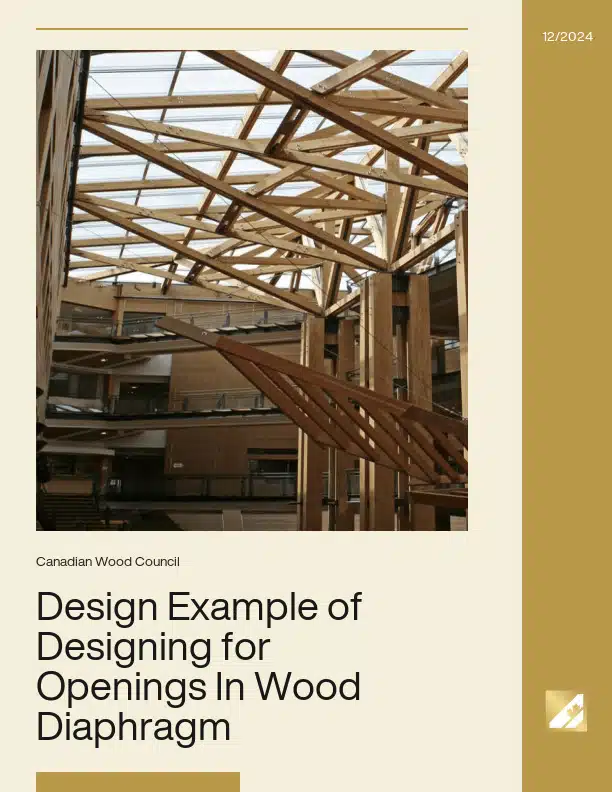
Sudbury, Ontario, located at the edge of a large geological structure known as the Sudbury Basin (a 1.85-billion-year-old meteorite impact crater), is home to Canada’s largest mining and smelting complex. By the 1970s, decades of mining and smelting nickel, copper and iron had reduced some 10,000 hectares of the surrounding area to desolation and had damaged watercourses for miles around. Sudbury is still a rich mining centre, but, as a result of a 90 % reduction in emissions and aggressive land reclamation, it has become a world centre for environmental science issues related to mining.
Working for years from four cabins, the Cooperative Freshwater Ecology Unit – a research joint venture involving Laurentian University, the Ontario Ministry of the Environment and the Ontario Ministry of Natural Resources – needed a new home to expand its specialized research into the protection, remediation, and restoration of freshwater lakes and ecosystems.
The resulting Vale Living with Lakes Centre for Freshwater Restoration vastly increases the Cooperative’s research capabilities. The major funders of the project included Industry Canada (Knowledge and Infrastructure Program), Ministry of Training Colleges and Universities, Vale – a global mining company, FedNor, Canada Foundation for Innovation, Ontario Research Fund, and the Northern Ontario Heritage Fund Corporation.
The Centre provides researchers and technicians access to laboratories, classrooms, offices, environmental bays and a watershed restoration facility. At the Centre, researchers examine long-term effectiveness of pollution reduction, and how a damaged lake ecosystem is able to dynamically heal itself over time.
As well as being a centre of excellence for critically important ecological research, the Vale Living with Lakes Centre is an extraordinary building with an exceptionally low environmental footprint. The project makes extensive use of wood products harvested and manufactured close to Sudbury, including structural, framing and decorative wood products.
Mid-Rise Construction In British Columbia – A Case Study Based on The Remy Project In Richmond, BC
Modern six-storey light-frame wood construction in British Columbia (BC) incorporates highly-detailed, researched and safe solutions. the engineering technology being adapted in the province is positioning BC at the forefront of the north American wood-frame construction industry. Mid-rise building solutions currently being developed and refined in BC will lead to more sustainable communities and affordable housing solutions that will positively change the face of north American cities.
Mountain Equipment Co-op Head Office – Vancouver, BC
Mountain Equipment Co-op (MEC) is one of Canada’s most progressive retailers, having embraced a philosophy of corporate, social and environmental responsibility since its creation in 1971.
Not simply a retailer, MEC engages in its own research and product development to ensure that it remains on the leading edge of sustainable practice. As early as 1994, MEC began manufacturing clothing using polyester fleece made from recycled pop bottles.
In the same year, anticipating a period of rapid expansion, MEC began to look seriously at the environmental impacts of its building program. Its board of directors endorsed a policy requiring environmental consultation for the construction and renovation of new and existing facilities. From modest beginnings, the outdoor retail cooperative now has over four million members and annual sales of more than $300 million.
With each new building project, MEC has endeavoured to advance its own sustainability agenda, and in this respect wood has played an important role. In 2002, the MEC Ottawa store was constructed largely from heavy timber salvaged from an existing building on the site; in 2008, the Burlington store was designed with a completely demountable heavy timber structure that earned it a Leadership in Energy and Environmental Design (LEED) credit for innovation; and in 2013, the North Vancouver store, another building in which wood features prominently, received a Canadian Green Building Award for its comprehensive approach to sustainability.
Social Services Administration Board – The District of Thunder Bay
The District of Thunder Bay Social Services Administration Board (the Board) delivers provincially mandated services to 13 communities in Northwestern Ontario. To help clients achieve self-sufficiency, the Board provides assistance to seniors, children, and people with addictions and administers social housing programs. In March 2012, the Board’s ability to help people was greatly enhanced by the opening of a new building in the Thunder Bay central business district. Before the new building came into service, services were delivered from three sub-standard locations, an arrangement that often required clients to travel from one location to another to get help. A feasibility study that examined the possibility of amalgamating the three offices considered three different locations for the new building. The site selected is in the centre of Thunder Bay, adjacent to the city hall and library (Figure 1). Initial resistance by the local community to bringing social services clients into the business district has been dispelled. Instead, it appears that the public and social services clients view a bright, progressive building as a positive influence. In addition, staff absenteeism has decreased. The building is wood post and beam construction with woodframe floors and infill walls. Glulam columns were left exposed. This aesthetically pleasing expression of the structure, combined with wood millwork and doors, provide a bright, positive atmosphere for staff and clients.
Cours Shearwalls
Aperçu du cours
Le cours Shearwalls présente aux apprenants le programme WoodWorks Shearwalls, un outil conçu pour la modélisation et l’analyse des structures à ossature en bois. Ce cours couvre la conception de structures complètes, y compris les murs, les toits et les ouvertures, tout en assurant une bonne répartition des charges et la stabilité de la structure.
Vous explorerez les capacités du programme à générer et distribuer les charges sismiques et de vent, à optimiser les configurations des murs de refend et à vérifier la conformité avec les codes du bâtiment.
Résultats de l’apprentissage du cours
A la fin de ce cours, vous serez capable de :
Concevoir et analyser des murs de refend à ossature bois à l’aide du programme Shearwalls, y compris la répartition des charges pour la résistance aux séismes et au vent.
Évaluer la performance des murs de refend et la conformité aux codes du bâtiment en interprétant les analyses structurelles générées par le logiciel.
Optimiser les configurations des murs de refend pour améliorer l’intégrité structurelle, en ajustant les matériaux et les paramètres de conception sur la base des meilleures pratiques d’ingénierie.
Structure du cours
Ce cours est composé de huit (8) leçons. Chaque leçon comprend un aperçu de la leçon, des résultats d’apprentissage, des vidéos pédagogiques, des questions d’évaluation et un devoir. Ces éléments vous permettront d’acquérir une expérience pratique dans l’utilisation du programme Shearwalls Woodworks pour des applications réelles.
Une fois que vous aurez répondu à toutes les questions d’évaluation et que vous aurez remis votre travail, un certificat d’achèvement vous sera remis numériquement.
Délai d’exécution
Ce cours est composé de dix-huit vidéos d’une durée totale de 90 minutes.
Pour compléter les évaluations de ce cours, vous pouvez vous attendre à passer ~ 95 minutes.
Téléchargement du logiciel
Pour suivre ce cours, vous devez télécharger une version d’essai du logiciel Shearwalls.
Suivez les étapes suivantes pour télécharger le logiciel :
Accédez à la page de téléchargement du logiciel en cliquant ici.
Cliquez sur le bouton « Télécharger maintenant » pour le logiciel Shearwalls.
Localisez et cliquez sur le téléchargement dans votre navigateur ou sur votre ordinateur.
Suivez les instructions de votre ordinateur pour terminer l’installation.
*Remarque : la version d’essai du logiciel n’est valable que pendant 10 jours à compter de l’installation.
The National Energy Code of Canada for Buildings (NECB) aims to help save on energy bills, reduce peak energy demand, and improve the quality and comfort of the building’s indoor environment. Through each code development cycle, the NECB intends to implement a tiered approach toward Canada’s goal for new buildings, as presented in the “Pan-Canadian Framework on Clean Growth and Climate Change”, of achieving ‘Net Zero Energy Ready’ buildings by 2030.
The NECB is available for free online; published by the National Research Council (NRC) and developed by the Canadian Commission on Building and Fire Codes in collaboration with Natural Resources Canada (NRCan). CWC maintains ongoing participation in the development and updating of the NECB.
The NECB sets out technical requirements for energy efficient design and construction and outlines the minimum energy efficiency levels for code compliance of all new buildings. The NECB applies to all building types, except housing and small buildings, which are addressed under Clause 9.36 of the National Building Code of Canada. The NECB offers three compliance paths: prescriptive, trade-off and performance.
The most cost-effective time to incorporate energy efficiency measures into a building is during the initial design and construction phase. It is much more expensive to retrofit later. This is particularly true for the building envelope, which includes exterior walls, windows, doors and roofing. The NECB addresses considerations such as air infiltration rates (air leakage) and thermal transmission of heat through the building envelope. Considering the different climate zones in Canada, the NECB also provides requirements related to maximum overall (effective) thermal transmittance for above-ground opaque wall assemblies and effective thermal resistance of assemblies in contact with ground, e.g., permanent wood foundations. In addition, the NECB specifies the maximum fenestration and door to wall ratio based on the climate zone in which the building in located.
As energy efficiency requirements for buildings are increased, wood is a natural solution to pair with other insulating and weatherizing materials to develop buildings with high operational energy performance and provide consistent indoor comfort for occupants.
For further information on the NECB, visit the Codes Canada at the National Research Council Canada.
Recognizing the barriers to adoption, the Canadian Wood Council has proactively mobilized a response strategy. As a first step, we have commissioned several studies to investigate and understand the workings of the Canadian and global insurance industry as it pertains to timber construction. As Canada’s voice for wood products, we have taken it upon ourselves to begin correcting the assumptions and misinformation associated with timber construction, while providing technical leadership to the insurance industry, the construction sector, and our partners
Overview of the Canadian Mass Timber Technical Guide
Course Overview
Join us for an introduction to a new, comprehensive Canadian technical reference guide to mass timber. Canada’s inherent building-with-wood culture lays a solid foundation for the continued growth of mass timber construction. Learn more about why mass timber is right for your next project, the design process and building systems, code acceptance, our expertise and more.
Learning Objectives
How mass timber can be incorporated into a variety of structural projects that typically utilize other materials.
Design considerations for utilizing mass timber and how the Mass timber guide can provide them with the information to navigate mass timber design.
How to use the mass timber reference guide for cross laminated timber and glue laminated timber design and construction.
Overview of the economic and sustainable benefits of mass timber construction.
Course Video
https://vimeo.com/1046519198
Speaker Bio
Orlagh McHugh – BSc, M.Eng, EIT Mass Timber Specialist Structurlam Mass Timber Corporation Vancouver/Vancouver Island, British Columbia, Canada
Orlagh McHugh is a Mass Timber Specialist at Structurlam Mass Timber Corporation, overseeing the Lower Mainland and Vancouver Island. Before relocating to BC almost a decade ago, Orlagh earned her Degree in Structural Engineering and Architecture at University College Dublin, Ireland, and went on to complete a Masters of Structural Engineering at the same institution.
With over 7 years of experience working with top Vancouver firms as a design engineer, she has contributed to a diverse catalogue of projects across a number of sectors, with a particular focus on wood and mass timber construction. Orlagh is inspired by the innovative nature of mass timber construction and keen to promote creativity, technology and sustainability in our built environment.
Ron McDougall Mass Timber Specialist Structurlam Mass Timber Corporation Western/Eastern Canada
Ron brings 30 years of heavy timber experience to the mass timber industry that combines a unique perspective on the evolution of hand built timber construction to the technologically advanced practices utilized in Structurlam’s state of the art production process.
Ron’s expertise is the facilitation of incorporating BIM practices in pragmatic and meaningful ways to ensure efficient construction of complex mass timber structures.
Offsite Construction in Ontario: A Practical and Diligent Path Forward
Course Overview
From the housing supply deficit to affordability issues and labour challenges, several conditions have been supporting a renewed interest for innovation in construction practices. Offsite construction is often identified as a promising approach to improve the way we build. This session explores the current market characteristics which are conducive to offsite practices, including the consistent shift towards multifamily construction in Ontario. It also identifies the numerous potential benefits of shifting the construction process from site to factory. The speakers will discuss underlying assumptions and conditions and questions such as: Are the promised benefits tangible and quantifiable? Do savings actually reach a project’s bottom line? Do all of the benefits apply to specific applications?
Learning Objectives
Identify market, labour, and housing conditions in Ontario that are driving interest in offsite and wood-based construction systems.
Evaluate the practical benefits and limitations of offsite construction using mass timber and panelized wood systems.
Assess when offsite construction provides measurable value at the project level, including cost, schedule, quality, and risk considerations.
Course Video
https://vimeo.com/1147113540
Speakers Bio
Mike Schmidt President Auto Construct Incorporated
A Tool & Die Maker with a Masters’ Degree in Business Administration, Mike understands manufacturing from the ground up. He spent his formative years as an executive in the automotive industry; working for world-class, multinational corporations such as Magna International and ArcelorMittal. In 2017, Mike established Auto Construct Incorporated (ACI), a management consulting firm, to accelerate the industrialization of residential construction. Specializing in the conversion from stick-built to offsite construction, Mike has led and facilitated the growth of several companies to become dominant players in their respective fields. ACI provides education, guidance, and implementation support in the areas of business development, manufacturing systems, technology selection, and factory start-ups. ACI serves a broad range of land developers, construction firms, homebuilders, and manufacturing companies throughout Canada and the United States.
Vertical Additions: An innovative pathway to delivering more homes
Course Overview
Discover the innovative approach to housing supply undertaken by Pathway Non-Profit Community Developments Inc. of Peel. The Arbor Mill expansion sets a remarkable precedent for other non-profit affordable housing providers who want to build more housing and can do it by adding additional units on top of their existing buildings. Globally, it is estimated that approximately 20-25% of existing buildings can support a vertical addition in wood, which is a comparatively light weight building material.
This novel approach removes the need to find new land to develop and has the added benefit of immediately integrating new residents into an existing supportive community. This project added 6 barrier-free, affordable apartments on top of a 35-year old, occupied residential building using prefabricated mass timber, delivering more affordable housing through the “gentle densification” of existing infrastructure.
In this webinar, the project team will discuss the architectural, structural, and design challenges of the project, including blending prefabricated mass timber construction methods with an older structure built with conventional materials. Key sustainability and construction considerations will also be highlighted. Don’t miss this opportunity to gain valuable insights from one of the first project teams in North America to pursue this innovative approach to housing delivery.
Learning Objectives
Participants will learn how Pathway, a non-profit community developer in Peel Region, created a plan to expand its housing portfolio while addressing tenant needs and priorities.
Participants will gain insights into the design and approval challenges of the project, including navigating site plan approvals, integrating mass timber, and meeting acoustic and fire safety requirements.
Participants will understand the structural considerations for vertical expansions, which include performing load assessments and evaluating structural options.
Participants will understand the mass timber fabricator’s process and the key considerations for successfully integrating prefabricated mass timber components into a project, including early involvement, securing production spots, and managing construction timelines.
Course Video
https://vimeo.com/1072356677
Speaker Bio
Roman Spektor General Manager Pathway Non-Profit Community Developments Inc. of Peel
Mechanical engineer by profession, Roman has been the General Manager of Pathway for over 25 years and has managed social housing projects for 35 years. Pathway Non-Profit Community Developments Inc. of Peel (Pathway) is an interfaith non-profit corporation that was incorporated in 1988. The Pathway organization is run by a volunteer board made up of members of the three founding congregations. Pathway owns and operates two apartment building in Mississauga constructed in the early 90s. Pathway’s two buildings, Forest Ridge and Arbour Mill, house 230 families and are funded by rental income and a government subsidy.
Pathway has also created a separate management company and manages other non-profit housing communities. Roman has coordinated with the volunteer board on all aspects of management of the buildings including budgeting, capital work and project management. Through the creation of programs for the residents, Pathway has created inclusive communities where all residents feel welcome.
Cathy has been a partner in the firm Tafler Rylett Architects since 1996 and is involved in all aspects of the firm’s work including client consultation, design, permit application, specifications and contract administration. Cathy is committed to producing thoughtful and environmentally responsible projects that are integrated with the surrounding landscape. The firm designs with a collaborative process, listening to their client’s requirements and budget and input from the surrounding community.
Cathy was chair of the OAA’s Committee on the Environment and is a member of the Toronto Alliance to End Homelessness (TAEH). The firm’s work includes supportive and affordable housing, offices, institutional and private residential projects. Major projects include supportive housing for Houselink Community Homes, offices for Doctors Without Borders, offices for the U of T Faculty Association, Tiny Treasure Montessori School and affordable housing for Pathway.
Craig Nicoletti, P.Eng. Partner, Structural Engineer Engineering Link Inc.
Craig is a Professional Engineer and Partner for the Structural Division at Engineering Link. He has been with Engineering Link since 2011 and brings more than 20 years of structural engineering expertise to his projects. During his tenure, Craig acquired a diverse portfolio of experience with wood projects that spans all sectors including commercial, recreational, industrial, hospitality, civic, and sporting facilities, in addition to heritage designated sites.
Stephen Balamut, B.Eng. Project Manager Element5
Stephen is a Civil Engineering Graduate of McMaster University. He began with Element5 as a designer and estimator, then moved into his current project manager position where he has overseen over 50 completed mass timber projects, from low- and mid-rise residential, to mixed-use and commercial. As a project manager, Stephen oversees the planning, coordination, and execution of Element5’s mass timber projects. He collaborates closely with architects, engineers, and contractors to ensure the structural integrity and sustainability of the mass timber components. Stephen is driven by a passion for contributing to sustainable projects that have a meaningful and lasting impact on people’s lives.
Advancing North American Mass Timber Projects: Harnessing the Strength of Local Expertise
Course Overview
As global adoption of mass timber construction accelerates, a growing number of solutions are available in the marketplace that can contribute to the success of your project. This session, presented by Simpson Strong-Tie, will explore some of the unique challenges faced by North American projects and some of the domestically developed solutions available to meet those challenges.
Learning Objectives
Understand the need for greater tolerance on concealed beam hangers, the importance of ensuring connectors are easy to install, and the specific requirements for large elements in North American buildings.
Understand the advantages domestic suppliers can bring to your project, including the rapid delivery of hardware to job sites.
Learn about the necessity for effective installation tools and processes tailored to the scale of large North American projects.
Learn about the need for effective moisture mitigation and the systems and strategies that can prevent unnecessary exposure of mass timber to the elements during construction.
Course Video
https://vimeo.com/968295117/90544c8a0f?share=copy
Speaker Bio
Adrian Mitchell Chair of Simpson’s internal Mass Timber Focus Market Committee Simpson Strong-Tie
Adrian is a mass timber and off-site business specialist with a principal focus on the rapidly expanding mass timber segment, for which he serves as Chair of Simpson’s internal Mass Timber Focus Market Committee. Adrian has spent the bulk of his 20-year career in the off-site, mass timber, and modular spaces, primarily as a business development leader and private consultant. With professional experiences ranging from heavy civil, oil and gas, high-end custom homes to large-scale mass timber missed-use projects and artificial intelligence in BIM, he has a unique and well-rounded background in wood and steel applications in off-site construction. Adrian is a native of Vancouver, Canada, and a graduate of the British Columbia Institute of Technology’s School of Business, he enjoys all the typical Canadian pastimes like playing hockey, building things from wood, and mountain biking.
Design Example of Designing for Openings In Wood Diaphragm
The effects of a single opening size and location on diaphragm shear, chord forces and framing member forces were investigated for a typical wood diaphragm. In conclusion, the maximum shear in the diaphragm with opening is greater than that in the diaphragm without opening. Increasing the distance between the edges of opening and diaphragm can reduce this increase in maximum shear significantly. When the dimension of the opening is no greater than 15% of the corresponding dimension of the diaphragm in both directions, and the distance of opening edge from diaphragm edge is no less than 3 times the larger dimension of the opening and that the portion of diaphragm alongside the opening satisfies the maximum aspect ratio requirement, the increase in maximum shear is less than 10%.
...an extraordinary building with an exceptionally low environmental footprint. The project makes extensive use of wood products harvested and manufactured close to Sudbury, including structural, framing and decorative wood products....
Mid-Rise Construction In British Columbia – A Case Study Based on The Remy Project In Richmond, BC
Modern six-storey light-frame wood construction in British Columbia (BC) incorporates highly-detailed, researched and safe solutions. the engineering technology being adapted in the province is positioning BC at the forefront of...
Mountain Equipment Co-op Head Office – Vancouver, BC
...four million members and annual sales of more than $300 million. With each new building project, MEC has endeavoured to advance its own sustainability agenda, and in this respect wood...
Social Services Administration Board – The District of Thunder Bay
...The building is wood post and beam construction with woodframe floors and infill walls. Glulam columns were left exposed. This aesthetically pleasing expression of the structure, combined with wood millwork...
Cours Shearwalls
Aperçu du cours Le cours Shearwalls présente aux apprenants le programme WoodWorks Shearwalls, un outil conçu pour la modélisation et l’analyse des structures à ossature en bois. Ce cours couvre...
...in contact with ground, e.g., permanent wood foundations. In addition, the NECB specifies the maximum fenestration and door to wall ratio based on the climate zone in which the building...
Recognizing the barriers to adoption, the Canadian Wood Council has proactively mobilized a response strategy. As a first step, we have commissioned several studies to investigate and understand the workings...
Overview of the Canadian Mass Timber Technical Guide
Course Overview Join us for an introduction to a new, comprehensive Canadian technical reference guide to mass timber. Canada’s inherent building-with-wood culture lays a solid foundation for the continued growth...
Offsite Construction in Ontario: A Practical and Diligent Path Forward
...and housing conditions in Ontario that are driving interest in offsite and wood-based construction systems. Evaluate the practical benefits and limitations of offsite construction using mass timber and panelized wood...
Vertical Additions: An innovative pathway to delivering more homes
...existing buildings can support a vertical addition in wood, which is a comparatively light weight building material. This novel approach removes the need to find new land to develop and...
Advancing North American Mass Timber Projects: Harnessing the Strength of Local Expertise
...oil and gas, high-end custom homes to large-scale mass timber missed-use projects and artificial intelligence in BIM, he has a unique and well-rounded background in wood and steel applications in...
Design Example of Designing for Openings In Wood Diaphragm
The effects of a single opening size and location on diaphragm shear, chord forces and framing member forces were investigated for a typical wood diaphragm. In conclusion, the maximum shear...