
Searching for: wood

Searching results for “wood”
520 results found...
Sort By Dropdown Icon

Part 2: Hold-Down Settings

Introduction

The video explains the key deformation sources affecting hold-down performance in shearwalls, including elongation, slippage, wood shrinkage, and bottom plate crushing. It demonstrates how users can modify hold-down properties in the Program’s database, adjust anchor rod lengths, and set shrinkage parameters. The video also covers bolt hole tolerances, additional deformation factors, and the option to override default hold-down settings. These features allow users to fine-tune shearwall designs for accuracy and structural integrity.

Learning Outcomes

By the end of this lesson, you will be able to:

  • Identify the four major sources of hold-down deformation in shearwall design and their impact on structural integrity.
  • Demonstrate how to access and modify hold-down properties within the Shearwalls Program, including adjusting anchor rod lengths and shrinkage parameters.
  • Analyze the effects of bolt hole tolerance, slippage, and crushing on hold-down displacement and apply appropriate settings to minimize deformation.
  • Apply the override hold-down property function to customize displacement and shrinkage values for specific project requirements.

Instructional Video (Part 2 of 3)

Video Run Time: 07:09 minutes

Part 1: 3-term vs. 4-term Deflection Equation

Introduction

The video explains the difference between the non-linear 4-term deflection equation from CSA 086 and the simplified 3-term linear approximation now available in Shearwalls Program.  The 3-term equation, adapted from the American SDPWS standard, combines the shear and nail slip components into a single shear term, making calculations linear.

While both equations yield the same deflection at 100% design capacity, the 3-term equation estimates higher deflections at lower loads and helps avoid convergence issues in the Shearwalls Program, particularly when distributing load between wood sheathing and gypsum wallboard. This simplification improves the accuracy and reliability of load sharing in shear wall design calculations.

Learning Outcomes

By the end of this lesson, you will be able to:

  • Differentiate between the 3-term and 4-term deflection equations used in shearwall analysis, including their assumptions and applications.
  • Explain the benefits of using the simplified 3-term deflection equation in structural design, particularly in program applications.
  • Analyze how load distribution varies when using the 3-term versus the 4-term deflection equation, especially in walls with multiple sheathing materials.
  • Evaluate the impact of equation selection on deflection accuracy and the ability to model real-world shearwall behavior in engineering design Program.

Instructional Video (Part 1 of 2)

Video Run Time: 04:05 minutes

Summary

Congratulations on completing the Connections Course!

Throughout this program, you have gained essential knowledge of the WoodWorks Connections Program and its role in designing and evaluating wood connections using bolts, nails, rivets, and shear plates.

You have explored key program features, including connection design, load input, capacity analysis, and optimization techniques, ensuring compliance with engineering standards and best practices. Through video tutorials, quizzes, and assignments, you have developed practical skills in creating efficient, structurally sound connections.

By the end of this course, you should now be able to:

  • Design and analyze wood connections using the WoodWorks Connections Program.
  • Evaluate connection capacity by interpreting software-generated results and ensuring compliance with industry standards.
  • Optimize connection designs by applying best practices and modifying configurations for improved structural performance.

To further strengthen your expertise, we encourage you to apply these skills in real-world projects and continue exploring advanced connection design techniques. If you have successfully met the course requirements, you will receive a Certificate of Completion to acknowledge your achievement.

Thank you for participating in the Connections Course—we hope this knowledge enhances your ability to design strong, efficient, and code-compliant wood connections!

Introduction to Connections

Introduction

This lesson provides an overview of the Connections Program. It demonstrates how to design new connections using bolts, nails, rivets, or shear plates, and how to check the capacity of existing connections. The video also highlights features such as producing fully dimensioned, CAD-quality drawings, generating material lists for fasteners and steel plates, and running designs for various connection types.

Learning Outcomes

By the end of this lesson, you will be able to:

  • Identify the key features and capabilities of the Connections Program, including its ability to design and analyze bolted, nailed, riveted, and shear plate connections.
  • Demonstrate how to generate fully dimensioned, CAD-quality drawings and material lists for connection designs using the program.
  • Evaluate the structural capacity of new and existing wood connections through the program’s analysis tools.
  • Apply the Connections Program to optimize connection designs for efficiency and compliance with engineering standards.

Instructional Video

Video Run Time: 04:44 minutes

Lesson 10 Assessment

Difficulty Level: 5/5

Estimated Time to Complete: 30 minutes


Problem Statement: Design of a 3-Storey Building

The figure below shows a floor plan and elevation along with the preliminary shear wall locations for a 3-storey light wood-frame building. It is assumed that some preliminary calculations have been provided to determine the approximate length of the wall required to resist the lateral seismic loads.

Given Data:

  • Building area: A = 12.2 m x 18.3 m
  • Seismic mass
    • Wr = 1.3 kN/m2 (roof) (Included dead load)
    • Ws = 0.5 kN/m2 (full snow load on roof)
    • Wf = 2 kN/m2 (floor)
    • The mass of walls are already factored in the mass of floors
  • Floor to floor height: h = 2.75 m
  • The roof is flat (2 degrees slope and no overhang)
  • Building is regular
  • Building is located in Castlegar
  • Site Class C soils
  • Importance factor = 1.0
  • Sheathing and framing
    • Use DF Plywood for sheathing
    • SS D.Fir. L (38 x 140) for framing
    • Stud spacing: To be determined
    • 4 Studs at each end of shearwall segments
  • Hold-down type : HDU8-SDS2.5
  • Use hold-downs on all segments
  • Apply hold-downs at all openings
  • Use the shearwall deflection to calculate rigidity, and distribute force on wall segments based on rigidity
  • Always linearize deflection equation

Design Requirement:

Use the software to design the shearwalls and provide answers to the questions below.


Question 1

The sheathing material information can be found in page 3 of the Design Results.

What is the minimum stud spacing required to meet the design criteria? *

Question 2

Based on the Design Summary Form, which of the following statements are true: *

Question 3

All shearwalls have sufficient design capacity for wind shear loads with a flexible diaphragm, but the story drift limit specified was exceeded on at least one level. *

Question 4

For seismic loads, all shearwalls have sufficient design capacity, but certain walls on Levels 1, 2, and 3 fail due to panel buckling or a non-ductile nail strength mode. *

Lesson 7 Assessment

Difficulty Level: 3/5

Estimated Time to Complete: 15 minutes


Problem Statement: Single Shearwall Design

The goal of this assignment is to design a single shearwall with multiple segments as shown below:

Given Data:

  • From the model, apply a seismic load V on the shearwall B-1, with a magnitude of 25kN
  • Vertical dead load on the wall (D): 10 kN/m
  • Use DF Plywood for sheathing
  • No1/No2 SPF (38 x 89) for framing
  • Stud spacing: 400 mm
  • 2 Studs at each end of shearwall segments
  • Hold-down type : HDU2 – SDS2.5
  • Use hold-downs on all segments
  • Apply hold-downs at all openings
  • Use the shearwall deflection to calculate rigidity, and distribute force on wall segments based on rigidity
  • Always linearize deflection equation

Design Requirement:

Use the software to design the shearwall and provide answers to the following questions: 


Question 1

The sheathing material information can be found in page 3 of the Design Results.

What is the minimum thickness of the DF Plywood needed to resist the applied loads (in mm): *

Question 2

Based on the Design Summary Form, the following statements are true: *

Question 3

The critical response ratios of all hold-downs is below 0.75. *

Question 4

What is the global deflection of the shearwall (in mm): *

Lesson 3 Assessment

Difficulty Level: 2/5

Estimated Time to Complete: 10 minutes


Problem Statement: Diaphragm Behaviours

A wood-frame industrial building is subjected to a net north-south unfactored wind load, as given below. All four perimeter walls act as shearwalls. The roof diaphragms are made of joists, spaced 600 mm on centre. The roof and floor diaphragms are supported by shearwalls “A” & “B” and seven glulam beams spaced 4 m O.C.

This assignment focuses on the wind load transmitted to first floor shearwalls (L1) by the floor diaphragm.


Select the most appropriate answer based on the software output and standard design requirements.

Question 1

Considering that the floor diaphragm is subjected to wind loading W  (in kN) and exhibits rigid behaviour, what would be the expression of the shear force induced in shearwall "B" (in kN)? *

Question 2

Considering that the floor diaphragm is subjected to wind loading W (in kN) and exhibits rigid behaviour, what would be the expression of the shear force induced in each segment of shearwall "A"? *

Question 3

Considering that the floor diaphragm is subjected to wind loading W  (in kN) and exhibits flexible behaviour, what would be the expression of the shear force induced in shearwall "B" (in kN)? *

Question 4

Considering that the floor diaphragm is subjected to wind loading W  (in kN) and exhibits flexible behaviour, what would be the expression of the shear force induced in each segment of shearwall "A"? *

Lesson 2 Assessment

Difficulty Level: 4/5

Estimated Time to Complete: 15 minutes


Problem Statement: Design of a Canopy Connection

A canopy is intended to be built at the entrance of the building described above. The canopy will be made of suspended systems. Each system will consist of twin glulam beams (Bei) and a slotted-in sawn-timber brace (Bri)  as shown below.


Given Data:

  • Beams (Bei): [2] Glulam – SP 20f-EX (80 x 342)
  • Brace (Bri): Sawn Timber (Beams and Stringers) – D. Fir-L   Select Structural (SS) (140 x 343)
  • All wood used for the canopy’s structure is untreated and seasoned.
  • All wood on the canopy (including the connection area) is expected to get wet during the service life of the building.

Design Requirement:

The connection at point B is of interest in this assignment. At that location (point B), beam Be1 is connected to brace Br1 through 4 bolts, as described on detail B. Use the software to design the connection assuming it is subjected to a tension force Tf = 25 kN.


Select the most appropriate answers based on the software output and standard design requirements.

Question 1

From your design summary, what is the minimum row spacing (in mm)? *

Question 2

Look for the parameter having the lowest resistance ratio, from your design results.

For a row spacing of 38 mm and a spacing within row of 76 mm, what is the failure mode of the connection. *

Question 3

For a row spacing of 38 mm and a spacing within the row of 76 mm, the side member's net tension resistance (TNr) provides the highest resistance, as it exceeds the applied factored load by a factor above 10. *

Connections Course

Connections Course

Course Overview

The Connections Course provides an introduction to the WoodWorks Connections Program, a tool designed to assist engineers and designers in the creation and evaluation of wood connections. This course covers the design of new connections using bolts, nails, rivets, or shear plates and explains how to assess their capacity.  You will gain an understanding of the program’s functionality, its application in real-world scenarios, and best practices for optimizing wood connections.

Course Learning Outcomes

By the end of this course, you will be able to:

  • Design and analyze wood connections using the Connections Program, incorporating bolts, nails, rivets, and shear plates.
  • Evaluate connection capacity and compliance with industry standards by interpreting program-generated results.
  • Optimize wood connection designs by applying best practices and modifying existing configurations for improved structural performance.

Course Structure

This course consists of ten (10) lessons. Each lesson is comprised of a lesson overview, learning outcomes, instructional videos, assessment questions and an assignment. Through these elements, you will gain practical experience in using the Connections WoodWorks Program for real-world applications.

Once you have completed all assessment questions and assignment submissions, a certificate of completion will be digitally awarded.

Time for Completion

This course is comprised of 2 videos for a total run time of 8 minutes.

To complete the assessments in this course you can expect to spend ~ 20 minutes.

Program Download

In order to complete this course you will need to download a trial version of the Connections Program.

Complete these steps to download the program:

  1. Navigate to the program download page by clicking here.
  2. Scroll down to the Connections section
  3. Click on the “Download Now” button for the Connections Program.
  4. Locate and click on the download either in your browser or on your computer.
  5. Follow the prompts provided by your computer to complete installation.

*Note: the trial version of the program is only valid for 10 days upon installation.

Shearwalls Course

Shearwalls Course

Course Overview

The Shearwalls Course introduces learners to the WoodWorks Shearwalls Program, a tool designed for modeling and analyzing wood-frame structures. This course covers the design of complete structures, including walls, roofs, and openings, while ensuring proper load distribution and structural stability.  

You will explore the program’s capabilities in generating and distributing seismic and wind loads, optimizing shearwall configurations, and verifying compliance with building codes.

Course Learning Outcomes

By the end of this course, you will be able to:

  • Design and analyze wood-frame shearwalls using the Shearwalls Program, including load distribution for seismic and wind resistance.
  • Evaluate shearwall performance and compliance with building codes by interpreting program-generated structural analyses.
  • Optimize shearwall configurations for enhanced structural integrity, adjusting materials and design parameters based on engineering best practices.

Course Structure

This course consists of ten (10) lessons. Each lesson is comprised of a lesson overview, learning outcomes, instructional videos, assessment questions and an assignment. Through these elements, you will gain practical experience in using the Shearwalls Woodworks Program for real-world applications.

Once you have completed all assessment questions and assignment submissions, a certificate of completion will be digitally awarded.

Time for Completion

This course is comprised of 23 videos for a total run time of 115 minutes.

To complete the assessments in this course you can expect to spend ~ 2 hours.

Program Download

In order to complete this course you will need to download a trial version of the Shearwalls Program.

Complete these steps to download the program

  1. Navigate to the program download page by clicking here.
  2. Scroll down to the Shearwalls section
  3. Click on the “Download Now” button for the Shearwalls Program.
  4. Locate and click on the download either in your browser or on your computer.
  5. Follow the prompts provided by your computer to complete installation.

*Note: the trial version of the program is only valid for 10 days upon installation.

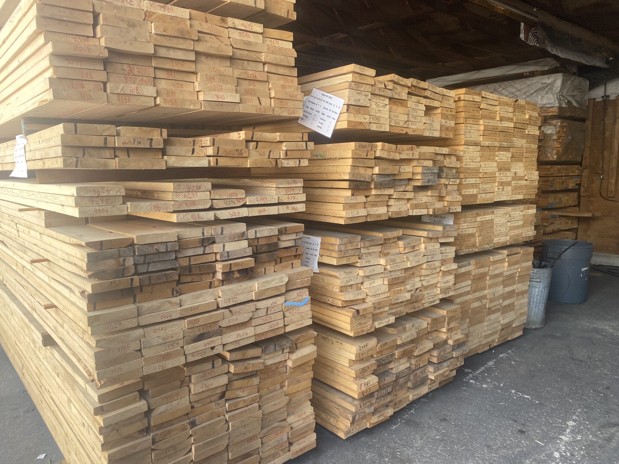
Updates to Hem-Fir (N) design values for dimension lumber

The Canadian Wood Council is proud to share the National Lumber Grades Authority (NLGA) latest updates to the design values for Hem-Fir (N) dimension lumber, effective April 1, 2025. These changes result from a routine reassessment of strength and stiffness properties, ensuring Hem-Fir (N) continues to meet structural performance expectations.

Key Points:

  • Minimal Practical Impact: The updated design values should not result in significant changes to the practical use of Hem-Fir (N) in most applications, maintaining continuity for builders, designers, and engineers.
  • Consistent Performance: Hem-Fir (N) remains a trusted and dependable choice for residential and commercial construction, with values that closely align with previous standards.
  • No Impact on Existing Construction: Structures built under previous building codes remain compliant.
  • The updates are reflected in the NLGA Standard Grading Rules for Canadian Lumber, CSA O86 – Engineering Design in Wood, and the National Design Specification® (NDS®) Supplement for Wood Construction.

For additional details, including specific design value changes, affected lumber grades, and implementation considerations, please refer to the Frequently Asked Questions (FAQ) document for Canada or the USA.

Download publication by Region:

Summary

Congratulations on completing the Sizer Course!

Throughout this course, you have gained a comprehensive understanding of the WoodWorks Sizer Program and its application in designing and analyzing beams, columns, wall studs, and CLT panels.

You have explored key program features, including load input, pattern loading, bearing design, lateral stability, and Concept Mode, while ensuring compliance with the National Building Code of Canada (NBCC). By engaging with video videos, quizzes, and assignments, you’ve developed practical skills in optimizing structural elements for safety, efficiency, and material performance.

By the end of this course, you should now be able to:

  • Design and analyze structural elements using the Sizer Program, considering load conditions and code compliance.
  • Evaluate load distribution and structural stability through pattern loading, lateral support analysis, and fire resistance adjustments.
  • Optimize structural designs using Concept Mode and refine detailed analyses in Beam and Column Mode.

To further your learning, we encourage you to apply these skills in real-world projects and continue exploring advanced design features in Sizer. If you have successfully met the course requirements, you will receive a Certificate of Completion to recognize your achievement.

Thank you for participating in the Sizer Course—we hope this knowledge enhances your expertise in structural wood design!

The 2025 Ottawa Wood Solutions Conference will be presented on February 5, 2025 at the National Arts Centre
Wood Design & Building Magazine, vol 23, issue 94
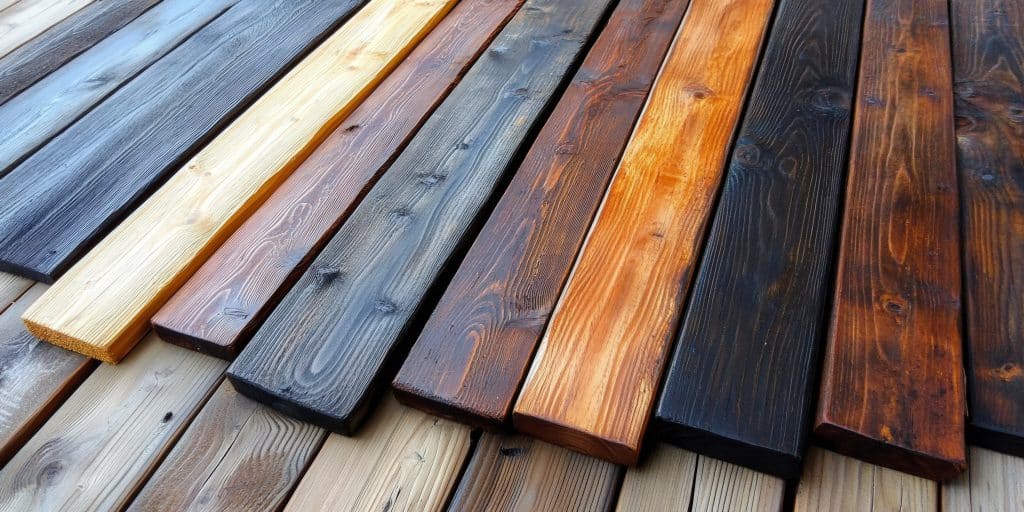
Choosing and Applying Exterior Wood Coatings
Wood’s Durable Heritage
Wood design in the National Building Code of Canada
fire-retardant-treated wood
Fire-Retardant-Treated Wood
Preservative Treated Wood
Wood in non-combustible buildings
Course Overview Discover the innovative approach to housing supply undertaken by Pathway Non-Profit Community Developments Inc. of Peel. The Arbor Mill expansion sets a...
Course Overview This presentation will provide an overview of reciprocal framing systems, showing examples of well-known structural forms such as lamella arches, as well as...
Course Overview Join us for an introduction to a new, comprehensive Canadian technical reference guide to mass timber. Canada’s inherent building-with-wood culture lays a...
Course Overview Following an introductory overview of building acoustics, the presenter will explore both airborne and impact sound transmission in mass timber buildings....
Course Overview Canadian Nuclear Labs’ Chalk River Laboratories comprise the largest single complex in Canada’s science and technology community. The site contains more...
Course Overview An overview of traditional, state of the art and innovative wood fasteners and connectors. This course is of particular interest to structural engineers and...
Course Overview Gestimat facilitates the assessment of the carbon footprint of buildings. Developed in Quebec for the Wood Charter and financed by the Fonds vert, Gestimat is...
Course Overview Through the example of the Biomass Power Plant at Hotchkiss School this presentation highlights distinctive and sustainable infrastructure. This Biomass Power...
Course Overview Dowel‐laminated timber is a next generation mass timber product commonly used in Europe, where it is also known as brettstapel. Panels are made from...
Course Overview As part of its work related to wooden buildings, FPInnovations recently published a comprehensive technical Guide for designing timber-concrete composite...
Course Overview A pilot project in Washington State tests the use of CLT to design and construct three modular classroom buildings in Western Washington. Funded by the...
Course Overview Follow our journey of introducing CLT into high end‐custom homes and mixed‐use residential projects in the Greater Vancouver Area. We’ll explore the...

Get Access to Our Resources

Stay in the loop and don’t miss a thing!

1
2
3

Get Access to Our Resources

Stay in the loop and don’t miss a thing!

What’s Your Occupation?

Help us personalize the content for you.

What Interests You the Most?

Help us personalize the content for you.

Filters

Expertise Icon
Field of Expertise
Province Icon
Province
Member Type Icon
WoodWork National Partners

Filters

Post Type Icon
Post Type
Persona Icon
Persona
Language Icon
Language
Tags Icon
Tags
Mass Timber Plus Icon Environment Plus Icon Safety Plus Icon Durability Plus Icon Design Systems Plus Icon Budget Plus Icon Construction Management Plus Icon Fire Resistance Plus Icon Tall Buildings Plus Icon Short Buildings Plus Icon
Date Icon
Date
Line Separator