Searching for: Wood

Searching results for “Wood”
520 results found...
Sort By Dropdown Icon

Unlocking Affordable Timber Innovations in Structure, Prefabrication, and Code

Course Overview

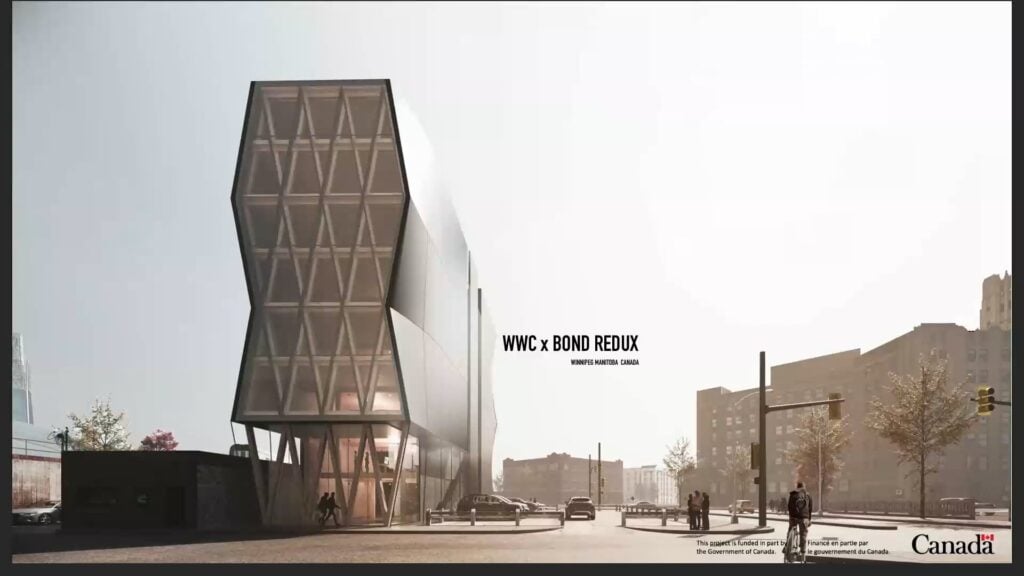
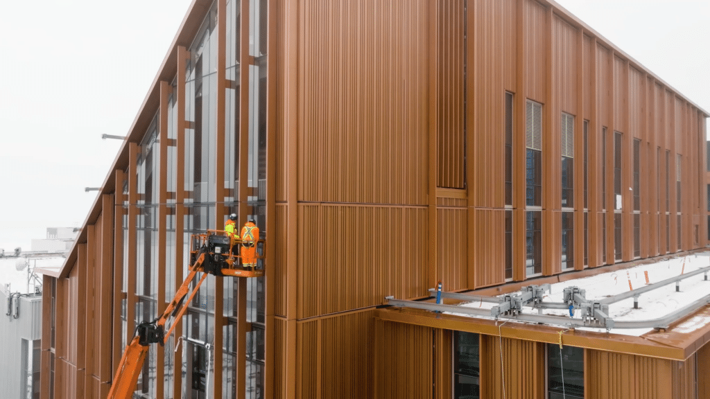
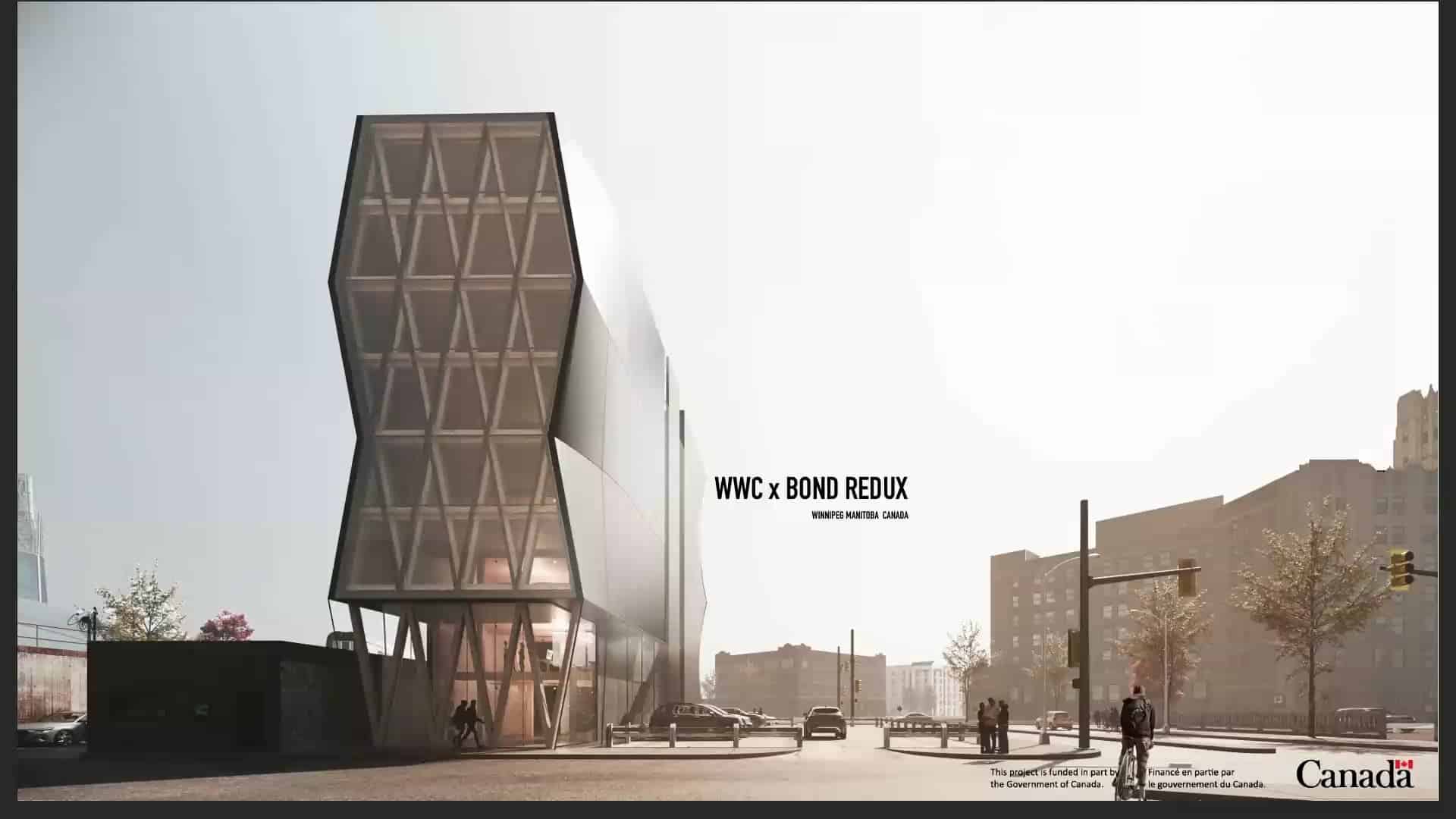
Bond Tower is a 7-storey mixed-use prototype that asks a critical question: how can mass timber be made cost-effective in the Prairies, where supply chains are limited, demand is low, and timber construction is often reserved for flagship projects. Funded by the Green Construction through Wood Program from Natural Resources Canada, the project develops both prototypes and a built demonstration to advance affordable timber solutions in a region underserved by the current market. 

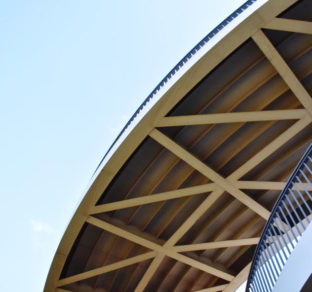
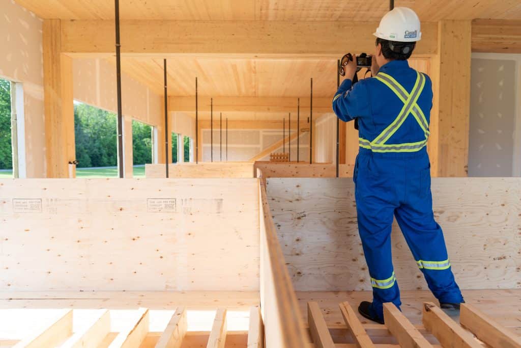
The design leverages nail-laminated timber (NLT) as its primary system, applied in diagrid trusses, floor assemblies, and shear walls. NLT presents a cost-effective alternative to other manufactured products and provides great versatility due to its custom nature. Lateral and gravity-induced forces are carried by a diagrid timber truss fabricated from readily available dimensional lumber and using simple mechanical fasteners. Floor assemblies comprised of NLT are constructed without a concrete topping or proprietary sound attenuation systems, reducing both cost and embodied carbon. Prefabricated wall panels, stairs, and modular service pods further minimize waste and construction time. 

Another challenge lies in building code classification. Currently, all structures above six storeys are deemed high-rise, requiring costly and difficult to achieve [in timber] two-hour fire-resistance ratings and fire-safety systems. The Bond Tower design team, working with code consultants, is developing an alternative solution that leverages the inherent 1.25-hour FRR of NLT floor assemblies. This approach suggests a pathway toward a new mid-rise category, making timber projects of seven or eight storeys more financially viable. Alongside a single-stair configuration, which can increase efficiency by reducing non-rentable floor area, these strategies point to a replicable model for affordable timber construction across Canada.

Learning Objectives

  1. Learn how NLT and prefabrication strategies can reduce cost, waste, and construction time, making timber more feasible in the Prairies.
  2. Explore structural detailing approaches that simplify connections and reduce cost, while addressing fire, durability, and acoustic performance in timber design.
  3. Examine how alternative solutions can improve the financial feasibility of 6–8 storey timber projects and support broader code updates across Canada.

Course Video

Speakers Bio

Sasa Radulovic, AIBC MAA OAA SAA AAA NSAA FRAIC LEED AP
Partner, Architect
5468796 Architecture

Sasa Radulovic co-founded the Winnipeg-based practice 5468796 Architecture with Johanna Hurme in 2007. A talented designer, Sasa guides the office in seeking projects that explore density, affordability, and sustainability through non-traditional means and a dynamic design approach. Recent institutional appointments include Visiting Professor-Morgenstern Chair with the Faculty of Architecture at the Illinois Institute of Technology in Chicago.

Ken Borton, MAA RAIC
Principal
5468796 Architecture

Oliver Brandt, P.Eng
Associate
Fast + Epp

Browse Resources

[facetwp facet="reset_filters"]
Sort by
[facetwp facet="sort_by"]
Type
[facetwp facet="post_type"]
Category
[facetwp facet="categories"]
Source
[facetwp facet="source"]
[facetwp facet="search"]
[facetwp facet="topic"]
[facetwp facet="pager_"]
[facetwp template="resources"]
[facetwp facet="pagination"]

Other Resources

Upcoming
Events

Stay updated on industry conferences, webinars, and workshops near you

Discover
E-Learning

Easy guides, helpful tools, and all the support you need to build with wood.

Free Technical
Support

Get help with tools, resources, and questions from our expert support team.

Design Tools
& Software

Tools to simplify wood design and project management with the latest technology.

Exposed Mass Timber Calculator

The Canadian Wood Council is pleased to introduce a new design tool: the Exposed Mass Timber Calculator.

Developed to support practitioners working with encapsulated mass timber construction (EMTC), this tool helps determine whether a compartment design aligns with the 2025 edition of the National Building Code of Canada (NBC).

By entering key information about your compartment layout—including size, wall configuration, mass timber elements, and encapsulation details—the calculator evaluates whether the design meets code requirements for exposed mass timber elements.

The tool allows users to:

  • Evaluate permissible percentages of exposed mass timber elements (beams, columns, walls, and ceilings)

  • Confirm compliance within suites or fire compartments

  • Identify potential code issues through automated warnings

  • Visualize compartment configurations with a generated 3-D model

  • Review encapsulation requirements and supporting notes


This practical calculator helps architects, engineers, and code professionals explore compliant design options more efficiently when working with mass timber construction.

Try the Exposed Mass Timber Calculator


Photo © Tom Arban

Federal Call for Proposals Opens Under $500M Forest Sector Transformation Investment

February 25, 2026 (Ottawa, ON) — The Canadian Wood Council (CWC) welcomes today’s launch of a national Call for Proposals by the Honourable Tim Hodgson, Minister of Energy and Natural Resources, under Natural Resources Canada’s forest sector transformation programs. Backed by a $500-million federal commitment, the funding is now open for applications from eligible businesses and organizations across Canada.

The call supports projects through four key programs:


“This strategic investment comes at a pivotal time for Canada’s forest sector,” said Rick Jeffery, President and CEO of the Canadian Wood Council. “These programs can help accelerate modernization, support innovation, and expand the use of advanced wood solutions—strengthening our industry and opportunities within our domestic market while positioning Canada as a global leader in sustainable construction.”

Wood solutions are central to Canada’s built environment and economic future. Expanded use of wood in construction can support housing supply goals, reduce embodied carbon, and create new opportunities for growth and value-added manufacturing.

The Canadian Wood Council encourages members, partners, and wood products manufacturers to explore these funding opportunities to:

  • innovate and diversify production
  • strengthen domestic demand
  • expand the use of wood in construction
  • support Indigenous participation
  • access emerging markets


About the Canadian Wood Council

The Canadian Wood Council (CWC) is Canada’s unifying voice for the wood products industry. As a national federation of associations, our members represent hundreds of manufacturers across the country. Our mission is to support our members by accelerating market demand for wood products and championing responsible leadership through excellence in codes, standards, and regulations. We also deliver technical support and knowledge transfer for the construction sector through our market leading WoodWorks program.


For media inquiries, please contact:

Sarah Hicks
Communications and Outreach Manager
Canadian Wood Council
[email protected]  | 1-705-796-3381

Limberlost Place: Video Case Study

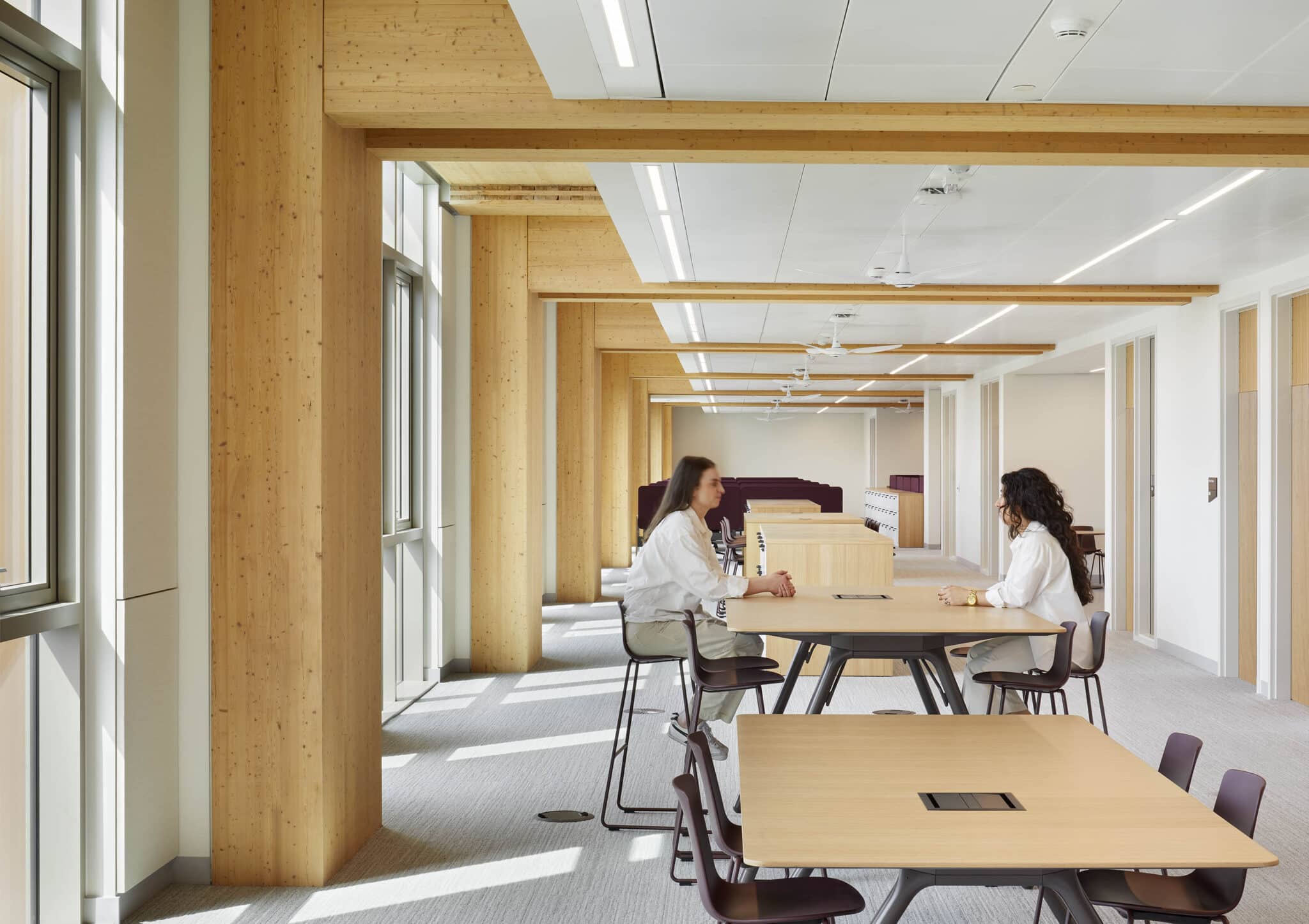
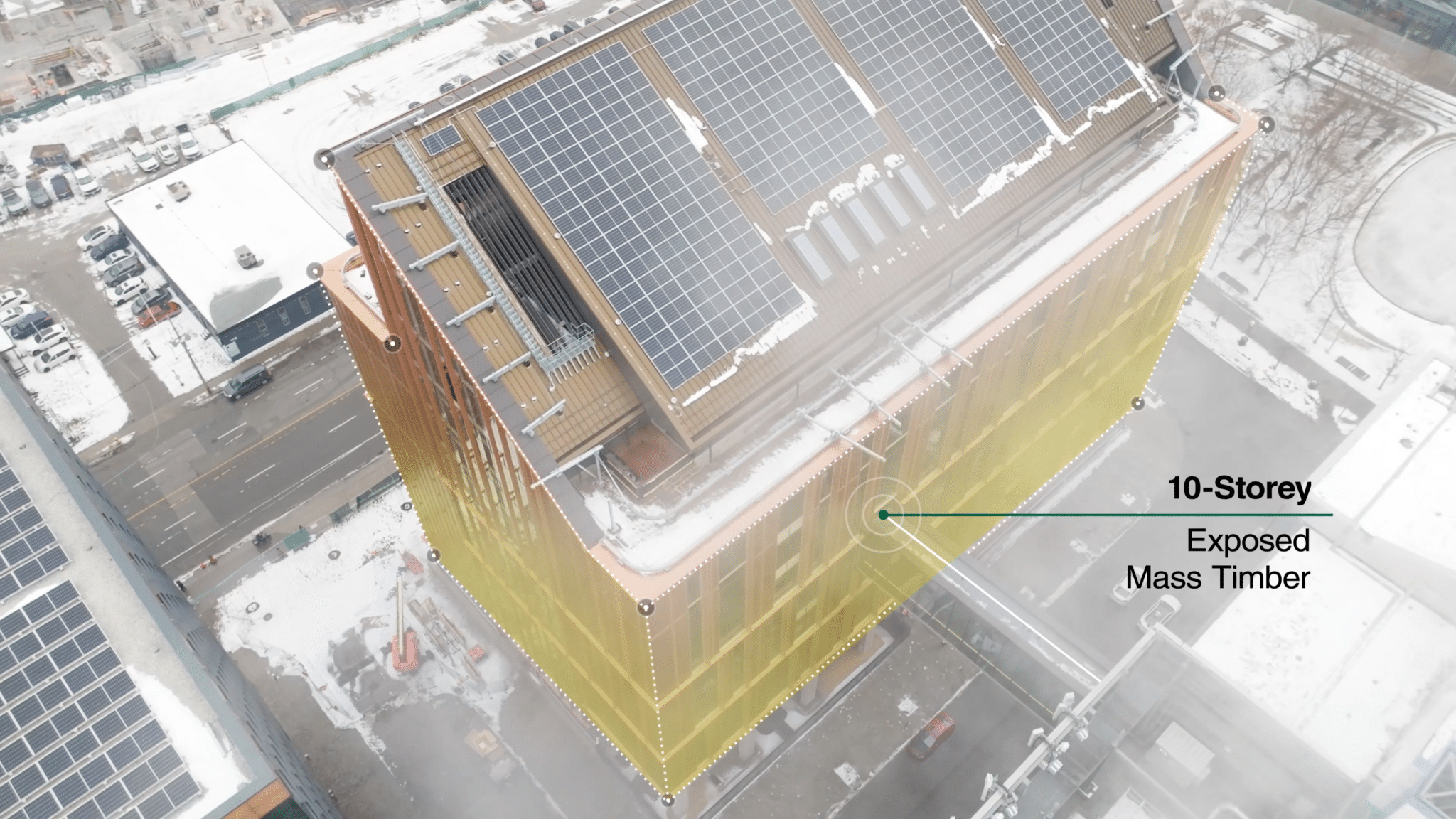
Discover the world’s first 10-storey exposed mass timber academic tower at George Brown College. This landmark project proves that sustainable, innovative, and human-centred design can stand tall together.


Building What’s Possible

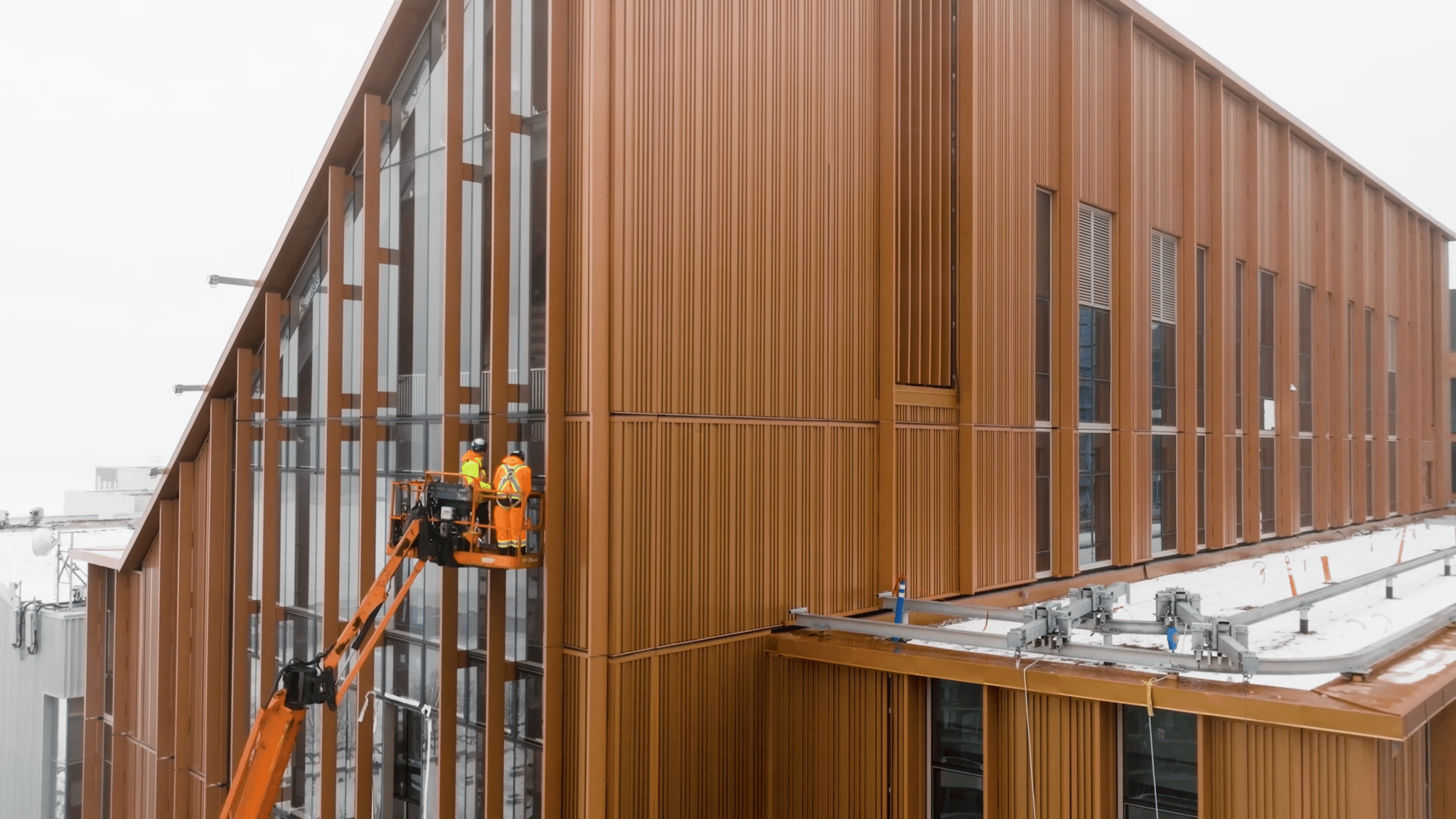
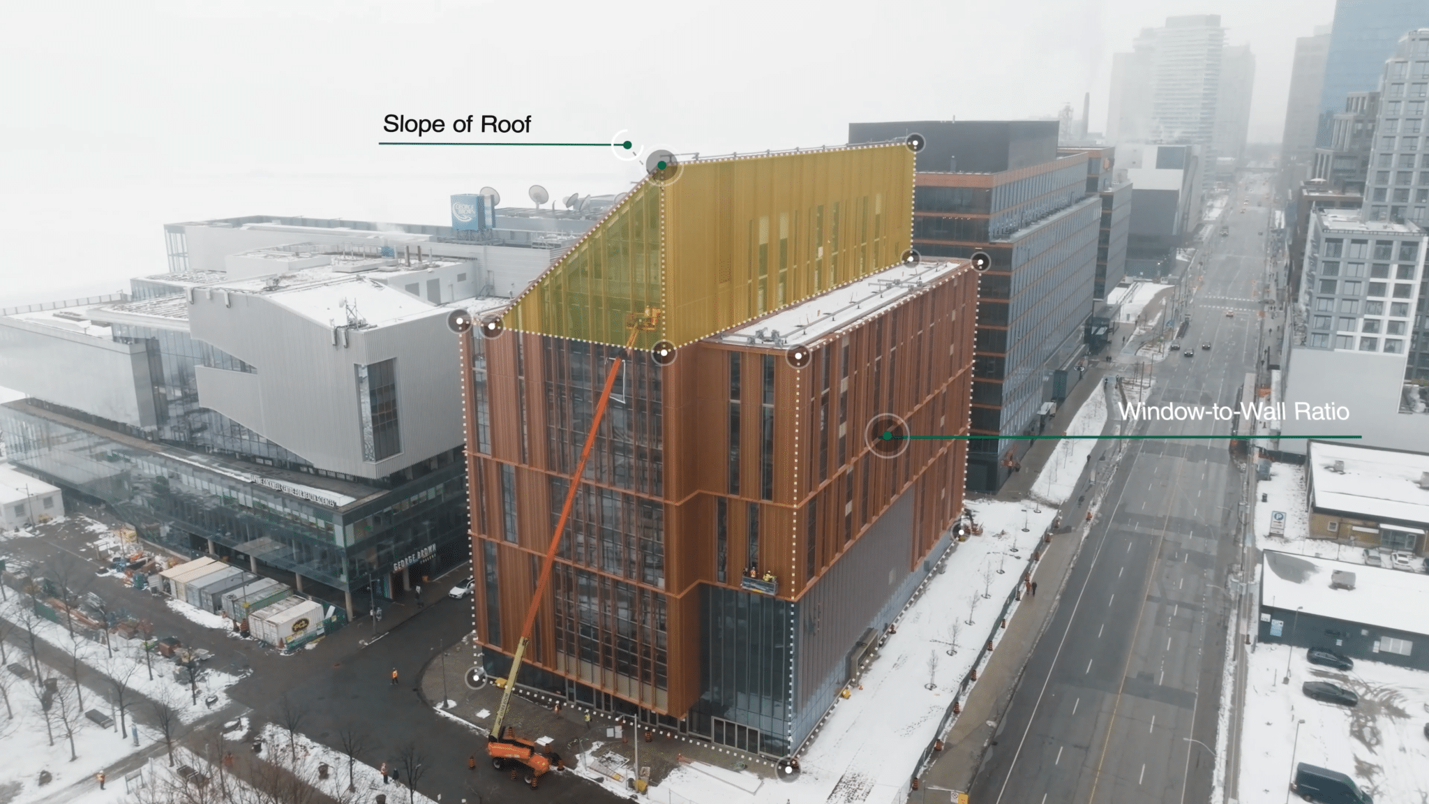
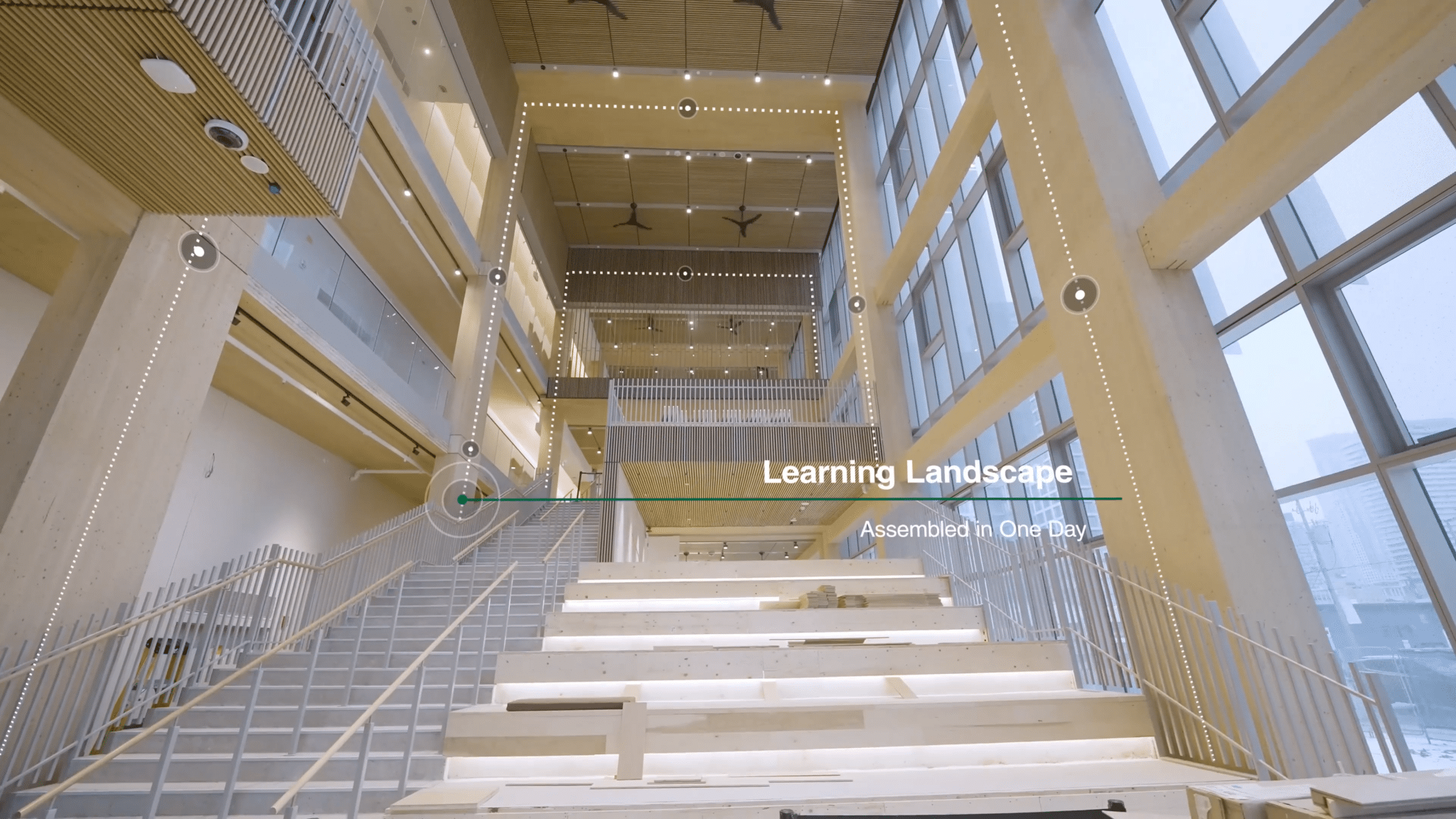
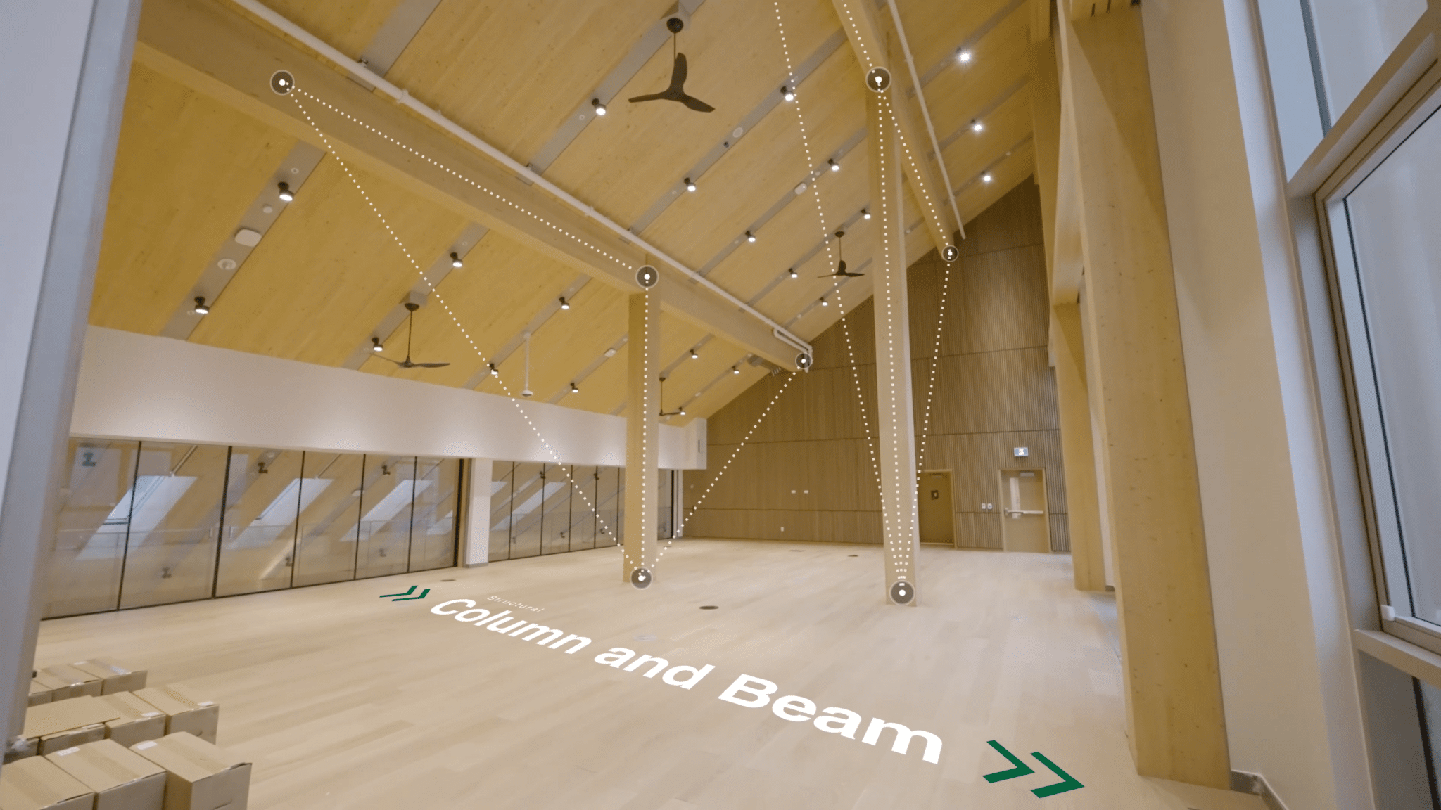
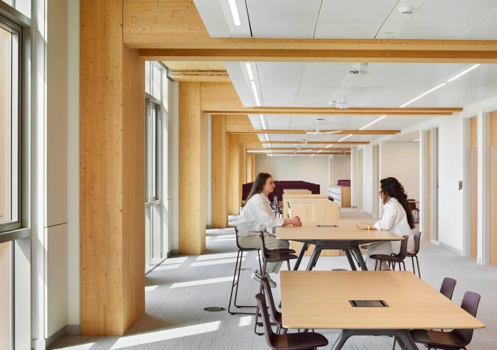
George Brown College’s Limberlost Place redefines what’s possible with mass timber construction. Rising 10 storeys above the college’s Toronto waterfront campus, this project is currently the largest exposed mass timber building of its occupancy type in the world.

Designed by Moriyama & Teshima Architects in joint venture with Acton Ostry Architects, built by PCL Construction, and realized in partnership with George Brown College, Limberlost Place demonstrates how innovation and collaboration can create a new model for sustainable development.


Sustainability at Scale

Mass timber is more than a building material — it’s a climate solution. This project shows that Canada’s design and construction industry is leading the way to a net-zero future.

By prioritizing wood construction, Limberlost:

  • Reduces carbon emissions significantly.
  • Creates healthy, biophilic spaces that support learning and well-being.
  • Proves that large-scale, low-carbon construction is achievable today.


Powered by Partnerships

Limberlost Place was made possible through strong collaboration. George Brown College worked alongside architects, engineers, and construction partners to deliver a bold vision: a living classroom where future designers, builders, and innovators can study inside the very spaces shaping tomorrow’s built environment.


A Blueprint for the Future

Limberlost Place is more than a single project. It’s a blueprint for how to build smarter and faster. By combining mass timber with hybrid engineering solutions, this project has set a new benchmark for low carbon construction in Canada and beyond.


Limberlost Place: Video Case Study

Limberlost Place: Video Case Study

Limberlost Place: Video Case Study

Limberlost Place: Video Case Study

Limberlost Place: Video Case Study

Limberlost Place: Video Case Study


This video case study was made possible through funding support from Natural Resources Canada and the Canadian Wood Council.

Shearwalls – US Version

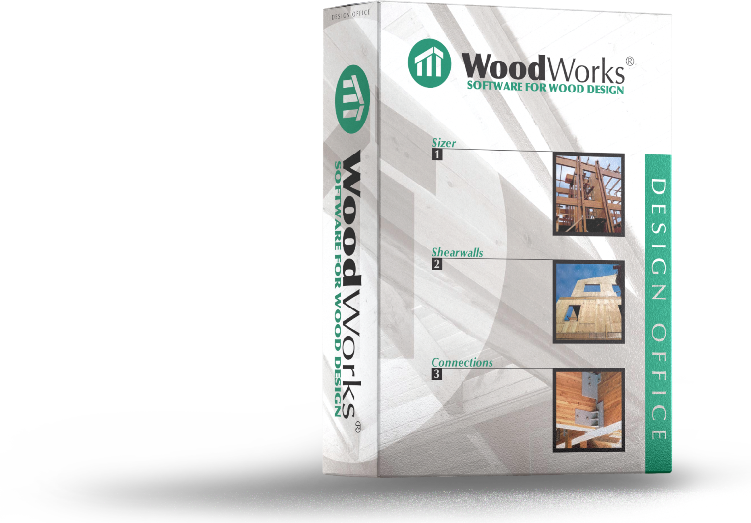
WoodWorks®

Shearwalls 2026

$275 /yearly subscription (USD)
Conforms to IBC 2024, ASCE 7-22, and SDPWS 2021

  • Automatically generates wind loads following the Directional or Envelope procedure in ASCE 7
  • Automatically generates seismic loads following the Equivalent Lateral Force procedure in ASCE 7
  • Distributes lateral loads to shear lines according to flexible and rigid diaphragm analyses
  • Distributes lateral loads within shear lines based on shear wall stiffness or capacity
  • Implements limitations and provisions for structural irregularities in ASCE 7
  • Designs full-height wall segments, force-transfer shear walls, and perforated shear walls with wood, gypsum, fiberboard and lumber sheathing
  • Designs shear walls for sheathing, nailing and hold-down connections
  • Optimizes shear wall design by iterating and automatically selecting the most economical sheathing and nailing patterns
  • Designs components & cladding for out-of-plane wind loads
  • Calculates shear wall deflection using “3-term” or “4-term” deflection equations
  • Checks story drift for wind and seismic
  • Determines anchor bolt, collector and force-transfer strap forces
  • Allows additional manual load inputs
  • Import .pdf, .bmp, .wmf and .emf files from AutoCAD as templates for floor layouts

  Detailed and transparent reporting of results, including:

  • One-page design summary of all critical design results and alerts
  • Shear wall materials summary table (for developing a shear wall schedule)
  • Individual shear wall ASD force vs resistance tables
  • Shearwall deflection and wind & seismic story drift tables
  • Hold down design tables
  • Sheathing and nail withdrawal design table for wind pressure
  • Collector and force-transfer strap force tables
  • Tabulated results for wind & seismic load generations and torsional analysis
  • And much more!


Did you know? 
Modelling a structure is quick and easy: start from a blank slate or use a pdf or wmf file as a template. See our video showing how typical buildings can be modeled in minutes!

Software Edition

A 10-day trial period activates upon installation
Image for illustrative purposes only. This is a digital product. No physical item will be provided.

Shearwalls - US Version

WoodWorks®

Sizer

WoodWorks® Sizer – Size beams, joists, columns, wall studs and panels constructed from lumber, timber, glulam, structural composite lumber, I-joists and CLT.

$210 /yearly subscription (USD)
A 10-day trial period activates upon installation

Software Edition

Image for illustrative purposes only. This is a digital product. No physical item will be provided.

Shearwalls - US Version

WoodWorks®

Shearwalls

WoodWorks® Shearwalls, design light wood frame structures up to 6 storeys. At the push of a button, wind and seismic loads are generated, forces are distributed, and shearwalls are designed.

$250 /yearly subscription (USD)
A 10-day trial period activates upon installation

Software Edition

Image for illustrative purposes only. This is a digital product. No physical item will be provided.

Shearwalls - US Version

Software Training Videos

WoodWorks Shearwalls | US Edition

Technical Specifications

General Information
Operational System
All versions currently supported by Microsoft OS.
Software Edition
US Edition
Subscription
$275 USD/Yearly
Software Capabilities
WoodWorks® Shearwalls is a powerful software for designing light wood frame structures up to 6 storeys, conforming to NBC and CSA O86. It automatically generates wind and seismic loads for buildings, distributes lateral loads between and within shear lines, and designs shearwalls with wood and gypsum sheathing. The software is capable of flexible and rigid diaphragm analyses and optimizing shearwall design by selecting the most economical sheathing and nailing patterns. Users can benefit from detailed and transparent design reports, including results for shearwall resistances, deflections, storey drifts, hold-downs, drag-strut forces etc.
SKU
WUSWC365
License Type
Concurrent
License Agreement
Click here to access the Woodworks Software® End User License Agreement.
WoodWorks US Shearwalls
Version 2026 (v.14.01) – Released in May 2026 and conforms to the NDS 2024, IBC 2024, ASCE 7-22, and SDPWS 2021
 
Click here to access the Change History for the US Shearwalls program.

Training Tab

The User Guide is a document created by the WoodWorks® Software Technical Support staff. The document includes instructions for operating the WoodWorks® programs as well as information on the software design settings.

Click here to download the Shearwalls User Guide
System Requirements Minimum Recommended Notes
Processor Speed
1 GHz
2 GHz
Single-core or equivalent performance in multiple-core processors.
RAM
1 GB
4 GB
Screen Resolution (Pixels)
1024 x 768
1440 x 900
Wide screen, adjust for other aspect ratios.
Free Hard Drive Space
80 MB
150 MB
Minimum is for download and installation. Recommended includes 100 typical project files.
Required Operating Systems
Microsoft Windows Home, Pro, Enterprise, and Education/SE editions. All versions currently supported by Microsoft.

Why professionals use it?

Shearwalls - US Version

Developed by Wood Design Experts

WoodWorks® Software is developed by Canadian Wood Council staff with expert knowledge and experience with building codes and wood design standards.

Shearwalls - US Version

Concurrent Licensing

Use a single license across multiple users without additional fees. Each license purchased grants one simultaneous use of the software.

Shearwalls - US Version

Add and design proprietary wood products (e.g., structural composite lumber, I-joists) with ease.

Shearwalls - US Version

Explore New Possibilities

There’s a New Way to Design Wood Buildings

Always Compliant with Canada and US Regulations

Built to align with Canada’s CSA O86 and NBC, as well as US codes and standards including IBC, ASCE-7, NDS, and SDPWS. Your projects meet safety and quality standards.

Access free technical support and resources to navigate wood design through WoodWorks® Software with ease and efficiency.

Access cutting-edge tools, resources, and expert guidance to navigate every stage of planning, design, and execution with ease and efficiency.

Easy to Use and Flexible Subscription Options

Enjoy user-friendly features and flexible subscription options designed to fit the needs of your project and your budget.

Frequently Asked Questions

WoodWorks ShearWalls FAQ

Can I input different heights for structure blocks at the same level?

Shearwalls requires that all structure blocks have the same height for each level and that all walls on one level have the same height. This means that the diaphragm is at the same height throughout the structure and that split-level conditions are not possible. There is no specific guidance in codes and standards on how to analyze split-level conditions. If you want to provide general design procedures for this condition, please contact WoodWorks Technical support. If you want to account for the strength and stiffness of different wall heights it is recommended to make a model of the structure based on the lowest or tallest wall height, and then create separate single wall project files as shown in tutorial 1 ( CDNU.S.) for the walls that have a different height.

 
Can I model proprietary shear resisting wall systems with different rigidities?

Features which allowed for this capability have been removed from shearwalls until a new feature which would allow the input of proprietary shear resisting elements can be incorporated into the program.

 
Can Shearwalls design L-Shaped and U-Shaped buildings?

Yes, with caution. Shearwalls has been programmed to follow the codes with respect to code defined “regular” shaped buildings. Certain “irregular” shapes will not provide expected results, and engineering intuition will be required to determine if the results are acceptable for each situation.

An example of an L-Shaped building design in the online video Tutorial 1 (US & CDN). This shape is handled adequately by the software.

Caution must be used in the case of a gap between two walls, where the gap is actually external to the building such as in a U shaped structure. Where the walls are along the same shearline and separated by a gap, diaphragm shearline force/unit length is assumed to continue across the gap (even though there is no diaphragm external to the building at the gap) and drag strut forces are shown. In other words, the software assumes the gap is really an opening such as a window or door and can transfer shear across it. This issue can be worked around by modifying the “Maximum Shearline Offsets” in the Settings, Design tab.

Designers may require shear or moment forces at specific points of interest. For example, for many types of connections, designers are required to check the shear capacity of the member at the connection location. WoodWorks® Connections provides the effective shear capacity of a wood member at a connection location. Using the Point of Interest function, a designer could determine the corresponding design shear force. This is also very useful to determine what the shear and bending is at a notch or hole.

How do I determine which walls have failed the design?

After running a model, the quickest method to determine if a shearwall has failed the shear resistance design check is to review the Design summary in the Results View. Use the Go To Table button to quickly navigate to the Design Summary.

When in Plan View of a model, walls which have failed the design check(s) will be highlighted in red. Walls will not appear red if there is a failure of the hold-downs along the shearline, however, the Design Summary will display whether or not the hold-downs have adequate capacity.

How are snow loads entered in Shearwalls?

In the US, where the design roof snow loads are less than 30 psf, they are not required to be included in seismic load calculations. For higher roof snow loads, a percentage of the snow load is used in the calculation for the weight of a structure (20% as per ASCE 7-10 – 12.7.2). In fact, local building authorities may overrule the code and require up to 100% of the roof snow load to be used. In Canada, 25% of the roof snow load is used in the calculation for the weight of the structure.

To include the correct snow load for seismic loads generation, input the total roof snow load and the percentage of roof snow load to be included in the Settings, Default Values tab “Weights for Seismic Load Generation”. Note, that modifying the default values in the Settings menu requires the user to start a “New” file to take effect.

In the “Generate Loads” dialog box, under the “Seismic Loads” column the total roof snow load entered in the Settings Default values will appear with a note under it indicating what percentage of that load will be used to calculate the total roof self-weight for weight calculation purposes. This can be modified as desired.

Remember to base the dead load and snow load on the horizontal projection of the roof. The snow load is considered to extend over the entire projected area of the roof minus the overhangs, as if it were a flat-roof load.

How can I model a shearwall that spans the height of both storeys in a 2 storey building?

This sort of condition can occur in lofts or in the foyer of a 2 storey structure. Shearwalls assumes that the structure will consist of platform frame construction and the diaphragm is continuous throughout the storey. To handle these situations, it is recommended to create two project files. For example, in the case of a 2 storey structure, with an open foyer that has a 2 storey wall at the front of the structure, one project file would consist of a 2 storey building that could be used to design all the single storey walls in the structure. In the locations where the 2 storey walls occurs, you could specify 1 storey shearwalls for the purpose of attracting loads. Then using the loads from the first project file, a single wall project file could be created as shown in tutorial 1 ( CDNU.S.) for the walls that span 2 storeys. The results from both project files could be compared to determine the appropriate design.

How do I determine which walls have failed the design?

After running a model, the quickest method to determine if a shearwall has failed the shear resistance design check is to review the Design summary in the Results View. Use the Go To Table button to quickly navigate to the Design Summary.

When in Plan View of a model, walls which have failed the design check(s) will be highlighted in red. Walls will not appear red if there is a failure of the hold-downs along the shearline, however, the Design Summary will display whether or not the hold-downs have adequate capacity.

How can I model a shearwall that spans the height of both storeys in a 2 storey building?

This sort of condition can occur in lofts or in the foyer of a 2 storey structure. Shearwalls assumes that the structure will consist of platform frame construction and the diaphragm is continuous throughout the storey. To handle these situations, it is recommended to create two project files. For example, in the case of a 2 storey structure, with an open foyer that has a 2 storey wall at the front of the structure, one project file would consist of a 2 storey building that could be used to design all the single storey walls in the structure. In the locations where the 2 storey walls occurs, you could specify 1 storey shearwalls for the purpose of attracting loads. Then using the loads from the first project file, a single wall project file could be created as shown in tutorial 1 ( CDNU.S.) for the walls that span 2 storeys. The results from both project files could be compared to determine the appropriate design.

How do I model complex roof shapes?

Roof blocks have two purposes in the software. They are used to create roof weight(s) that contribute to the total weight of the structure which is used to generate the seismic loads, and based on their shapes, roof blocks are also used to generate lateral wind loads for the purpose of designing the main wind lateral force resisting system. Shearwalls does not automatically generate wind uplift loads. Taking time to draw complex roofs with many hips and valleys that would require 8 or more roof blocks is time consuming and may not be necessary for structural analysis. Instead, the complex roof could be simplified to fewer roof blocks which generically model the shape of the roof. For an example an discussion of a complex roof where this would be applicable.

How do I modify an exterior wall segment to be specified as non-shear?

To modify a wall segment to be specified as non-shear, the Design in group feature must be turned off. Below are the 4 steps to complete.

1. Split exterior wall into multiple segments by tracing over the wall.
2. Click on the wall segment you would like to designate as non-shear.
3. Uncheck the “Design in group” box in the walls view.
4. While still in walls view, modify the wall segment type to “non-shearwall”.

A standard wall can be saved with the “design in group” feature already disabled.

How do I view different Low-Rise and All-Heights wind load cases?


WoodWorks® U.S. Shearwalls is capable of generating wind loads following ASCE 7-10 Envelope (Low-rise) Procedure (ASCE 7-10 Chapter 28, Figure 28.4-1) or the directional (All-heights) procedure (ASEC 7-10 Chapter 27, Figures 27.4-1 and 27.4-8).

For low-rise wind loads the software calculates load cases for wind acting on any corner of the building. Once wind loads are generated, arrows will appear in the plan view on the windward corners of the building representing the unfactored wind loads for the load case displayed. Review the legend at the bottom of the plan view screen. Other load cases may be viewed using the Show button. The wind loads can be displayed for the main wind force resisting system (MWFRS) about either the North – South or East – West directions. By default, the software will first display the West to East, South to North wind direction, but this can be modified to which ever combination. Critical force direction can be displayed after the analysis is run. Wind loads can be displayed for both wind load cases A or B. Shearwalls automatically uses the worst case wind loads when completing the design of the shearwalls.

The All Heights procedure is readily applicable to a wide range of building geometries. The software can handle almost any configuration following this procedure as wind loads are calculated on each wall and roof surface independently. Once wind loads are generated, arrows will appear in the plan view around the building representing the unfactored wind loads for the load case displayed. Review the legend at the bottom of the plan view screen. Other load cases may be viewed using the Show button. The wind loads can be displayed for the main wind force resisting system (MWFRS) about either the North – South or East – West directions. By default the software will first display the West to East, South to North wind direction, but this can be modified to which ever combination. Shearwalls generates both case 1 and case 2 wind loads simultaneously, and uses the heaviest of these loads as the minimum load case. Case 1, Case 2 and minimum load can be displayed in plan view. Shearwalls automatically uses the worst case wind loads when completing the design of the shearwalls in the model.

For the Canadian edition of shearwalls, it is possible to generate wind loads following Figure I-7/8 (Low rise method) or Figure I-15 (unnamed all heights method).

How do I view the Wind and Seismic equations used to generate the loads Shearwalls?

In WoodWorks® Shearwalls, when you click the “Generate Loads on selected levels” button on the “Generate Loads” form, a log file detailing the load calculations is created. The log file will automatically become available at the top of the Shearwalls menu. The log file is also automatically saved under the same name of the project file (with extension .log) in the same folder. Before the analysis is run, the log file includes information on how both the wind and seismic loads were generated. A summary of the site specific wind and seismic parameters, list of equations and resulting calculations are provided. If seismic loads have been generated, once the analysis of the model is run, the log file will update to include the torsional analysis results for the seismic loads.

How many structure blocks do I need to create a model?

Structure blocks are used to quickly establish the exterior perimeter of the structure. Multiple structure blocks are meant to be utilized when there are portions of a structure which vary in height (ie. Two storey house attached to a one storey garage). It is not necessary to draw the structure blocks to match the roof shape as it is possible to draw as many roof blocks as desired once in roof block view.
Using multiple structure blocks is not necessary and can over complicate a model. It may be possible to achieve the correct shape of the structure once in walls view by splitting and shifting exterior walls. Split walls by tracing another wall on top of an existing one, then move the wall by clicking on the segment, then holding the shift key to move the wall segment.
The method for splitting and moving walls is shown in US Shearwalls tutorial 2  and in CDN Shearwalls tutorial 2. Tutorial 11 in the user guide provides further discussion and demonstration of when and how to utilize structure blocks.

Some local building codes require that the seismic forces be multiplied by “1.35”, and that the sheathing capacities be equal to those listed in the UBC 97 (ie. multiplied by “0.75”). How does Shearwalls comply with these requirements?

Click Settings/Design, under local building code capacity modification, it is possible to adjust the plywood sheathing shear strengths. The default values are 1.0, but can be modified to conform to local conditions. For example, Los Angeles Building Code mandates or at one time mandated a 75% reduction in shear capacities for seismic design. If the factor is still in effect, users should save or enter “0.75”as their default local building code modification factor for seismic loads. Similarly, there are counties in the Southeast USA that require a reduction in shear strength for high wind loads. Users in these areas should check their local building codes and apply the factor if the locally mandated shear strength differ from those published in the IBC or SDPWS.

What do the “Maximum Shearline Offsets” shown in Design Settings represent?

WoodWorks® Shearwalls allows users to specify the maximum plan or elevation offset for walls to be considered on the same shearline. These settings are found under Maximum Shearline Offset in the Settings, Design tab. The maximum plan offset is dependent on the specified plan offset and elevation joist depth. By default, Maximum Plan Offset in the plan is set as 0.5 ft (0.15m) and the Elevation offset is set as 1 joist depth, to account for errors while drawing walls. The above values are recommended to provide tolerance for the automatic shearline generation routine. However, the software allows the user to change the default values at their discretion For example, the CWC Engineering Guide for Wood Frame Construction, which provides guidance on the design of light-frame wood structures which meet the requirements of a Part 9 prescriptively design structures, allows for a maximum shearwall plan offset of 4 joist depths, up to a maximum of 1.2 m ( 2014 Engineering Guide for Wood Frame Construction Part B Figure 10.1.5). Similarly, in the US, the Wood Frame Construction Manual allows shearwall plan offsets up to 4 feet ( WFCM 2015 Clause 2.1.3.3.c.). The maximum shearline offset feature can be utilized to match similar requirements when modelling a structure.

When I try to print specific pages in Shearwall’s Results View, the wrong pages are printed.


This is a known issue with the Shearwalls program. When printing the design results, Shearwalls reduces the number of pages compared to the number of pages listed and displayed in the Results view. To avoid the issue, it is recommend to print the Results to a pdf, then print the desired pages.

 
Looking for WoodWorks ShearWalls Support?

Let us Know How We Can Help You

Our technical team is available to support you throughout your WoodWorks Software® journey during regular office hours. 

Other Products

Take a moment to explore our other software products, designed to assist you in designing your next project.

Shearwalls - US Version
WoodWorks® Sizer

With WoodWorks® Sizer, size beams, joists…

$210 /yearly 10-day trial period available.

Shearwalls - US Version
WoodWorks® Shearwalls

With WoodWorks® Sizer, size beams, joists…

$250 /yearly 10-day trial period available.

Shearwalls - US Version
WoodWorks® Connections

With WoodWorks® Sizer, size beams, joists…

$60 /yearly 10-day trial period available.

International Perspectives on Sustainable Housing Development

Course Overview

Around the world there is a significant and growing housing shortage that is exacerbated by rapid urbanization and population growth. This challenge demands innovative solutions that prioritize sustainability, occupant comfort, and efficient land use. This panel discussion brings together three internationally renowned architects: Francine Houben (Mecanoo, the Netherlands), Christophe Ouhayoun (KOZ Architects, France), and Geoff Denton (White Arkitekter, Sweden) to explore their approaches to sustainable housing. Each panelist will share their unique perspective on how to address housing shortages and sustainable densification, offering insights into the latest design strategies, materials, and technologies that can contribute to more resilient and equitable urban environments. Join us for a dynamic conversation that will delve into the future of housing and the role of architecture in creating livable, sustainable cities. 

Learning Objectives

  1. Understand how international architects approach sustainable housing development, including wood‑based construction, urban densification, and low‑carbon strategies.
  2. Compare differing regulatory, cultural, and construction‑industry conditions that influence mass timber, modularity, prefabrication, and approval processes in Sweden, France, and Canada.
  3. Identify urban‑design principles used to create healthy, community‑oriented neighborhoods.

Course Video

Speakers Bio

Francine Houben
Founding Partner, Creative Director
Mecanoo, the Netherlands

Francine Houben is founding partner of Mecanoo (1984) and has led the firm to success in The Netherlands and abroad, amassing a portfolio of work that is wide-ranging, inspired by global challenges and with a sustainable view on society. Mecanoo combines the disciplines of architecture, urban planning, landscape architecture and interior design to produce unorthodox design solutions born from a strong sensitivity to context and a highly interdisciplinary design process. Each of her projects illustrates the four fundamental elements of her architectural vision: People, Place, Purpose, Poetry. Francine Houben was professor of mobility aesthetics at Delft University of Technology and taught at the universities of Harvard, Yale and Mendrisio. As curator of the First International Architecture Biennale Rotterdam (2003), she brought the theme of the aesthetics of mobility to the forefront of international design consciousness. Francine holds Honorary Fellowships of the Royal Institute of British Architects (RIBA), the American Institute of Architects (AIA), the Royal Architectural Institute of Canada (RAIC) and was granted lifelong membership to the Akademie der Künste in Berlin as well as receiving the International Honorary Fellow Award by the Architecture Institute of Taiwan. In 2014 Francine was named Woman Architect of the Year by the Architects’ Journal and in November 2015 Queen Máxima of The Netherlands presented her with the Prins Bernhard Cultuurfonds Prize for her wide-ranging career. Francine was awarded Honorary Doctorates from the Université de Mons, Belgium (2017) and the Utrecht University (2016). In 2018 she received the BNA Kubus Award for her oeuvre; the International Prize, Prix des Femmes Architectes (2019) and distinguished with the TU Delft Alumnus of the Year (2020). In 2024, King Willem-Alexander appointed Francine Houben as a Knight in the Order of the Netherlands Lion.

Christophe Ouhayoun
Founding Partner Architect
KOZ Architects, France

Christophe Ouhayoun is a graduate of the École Nationale Supérieure d’Architecture de Paris-Belleville. He currently serves as a State Architect Advisor in the Aveyron department. In 1999, he co-founded KOZ Architectes with Nicolas Ziesel. A pioneer in wood architecture since 2001, he recently delivered Lot E of the Paris 2024 Athletes’ Village as co-coordinator within the Nexity-Eiffage team. In addition to his architectural work, he co-founded: KOZTO, a workshop dedicated to the creation of up-cycled furniture. PLAN01, a collaborative “”second office”” active from 2003 to 2014, in partnership with Atelier du Pont, BP Architectures, and Philéas. PLAN02, an integrated environmental consulting firm. Alongside his private practice, Christophe Ouhayoun works as a visiting professor at the École Nationale Supérieure d’Arts et Métiers and at the École spéciale d’architecture de Paris.

Geoff Denton
Partner Architect
White Arkitekter, Sweden

Geoff Denton is an architect and urban designer who has led residential, educational and mixed-use urban design and architectural projects across the UK, Europe and North America. Educated at Sheffield University in the UK, his career in Sweden notably led him to the role of lead architect for the implementation of Greenwich Millennium Village for Ralph Erskine Architect. This project marked the beginning of his focus on socially and environmentally sustainable urban development and regeneration. He joined White Arkitekter in 2011 and is now a partner and member of the board of directors. During his time at White he has led award winning urban design projects and was responsible for starting White Arkitekter’s London Studio. The studio has been built on the goal to share knowledge and experience of sustainable development and offsite fabrication methods used throughout the Nordics. Key projects developed during the first years of the London studio include the Climate Innovation District in Leeds and the Gascoigne estate regeneration in London. Geoff is now based in Stockholm where he works with diverse complex international projects. His approach to architecture is collaborative and he strongly believes that good design solutions are very much about creating places where people feel secure and invigorated.

Building Success: The Nshwaasnangong Child Care and Family Centre Story

Course Overview

This session will explore the transformative journey of the Nshwaasnangong Child Care & Family Centre, a project that began as a response to the Truth and Reconciliation Commission’s Calls to Action. Led by Two Row Architect and supported by various community partners, the project highlights the innovative use of mass timber to create culturally meaningful and sustainable spaces. Attendees will learn about the collaborative design process, the integration of traditional materials with modern building practices, and the impact of the centre on the local community. The session will also provide insights into accessing technical resources and project support for wood construction through WoodWorks Ontario.

Learning Objectives

  1. Explore the use of mass timber to create culturally meaningful and sustainable spaces, demonstrated through the Nshwaasnangong Child Care & Family Centre.
  2. Understand the collaborative design and prefabrication process, integrating community input, modern construction practices, and workflow planning with mass‑timber manufacturers for complex geometries.

Course Video

Speakers Bio

Matthew Hickey
Architect
Two Row Architect

Matthew Hickey is Mohawk from the Six Nations First Nation and is a licensed architect with 12 years of experience working in an on-reserve architecture firm. He received his Masters of Architecture from the University of Calgary and his Bachelor of Design from Ontario College of Art and Design, winning both the Alberta Association of Architects Presidents Medal and the Medal for Best Thesis, respectively. Mr. Hickey’s focus is on regenerative design – encompassing ecological, cultural, and economic principles. His research includes Indigenous history and the adaptation of traditional sustainable technologies to the modern North American climate. He currently instructs at OCAD U, for the OAA and the Canada Green Building Council.

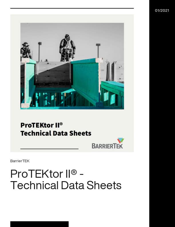
ProTEKtor II® – Technical Data Sheets

The ProTEKtor II® Technical Data Sheet provides detailed product and performance information for BarrierTEK’s ProTEKtor II® fire-protectant treatment used on wood frame and sheet components. The document is intended for designers, builders, specifiers, and code officials who require clear, concise technical data to support product evaluation and specification.

The TDS outlines key product characteristics, application parameters, and performance attributes for treated wood framing members and sheet goods, including compatibility considerations and relevant fire performance data. It serves as a practical reference for understanding how ProTEKtor II® is applied to enhance fire protection in both exposed and concealed wood-frame assemblies.

Developed as a technical reference, this data sheet supports accurate specification and informed use of ProTEKtor II®, helping project teams integrate fire-protectant-treated wood products into wood-frame construction with confidence and consistency.

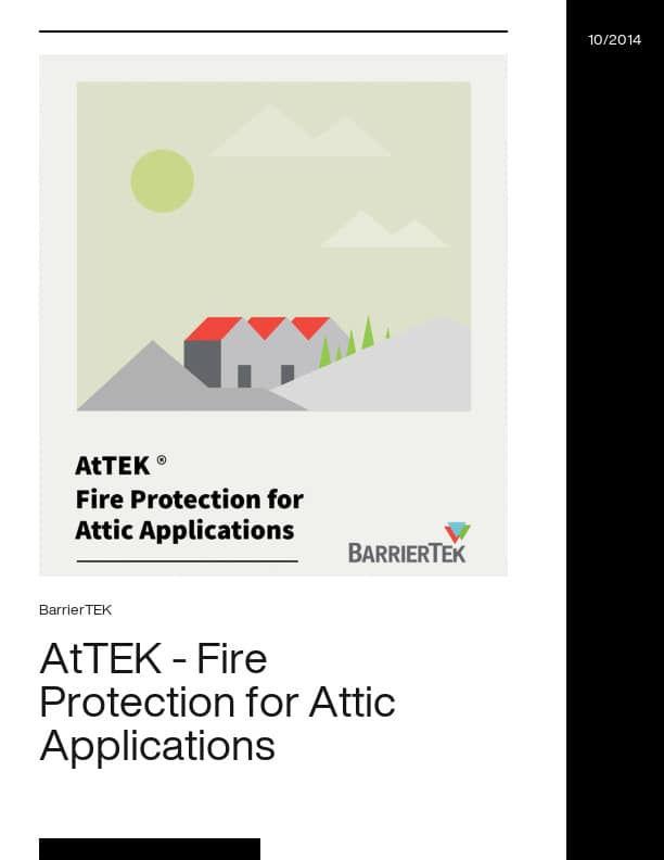
AtTEK – Fire Protection for Attic Applications

The AtTEK® – Fire Protection for Attic Applications Technical Data Sheet provides detailed product and performance information for BarrierTEK’s AtTEK® fire-protectant treatment used in wood-frame attic assemblies. The document is intended for designers, builders, specifiers, and code officials requiring concise technical data to support product evaluation and specification.

The TDS outlines key product attributes, application parameters, and performance characteristics relevant to attic framing components, including treatment coverage, compatibility with wood products, and applicable fire performance considerations. It serves as a quick-reference resource for understanding how AtTEK® is used to enhance fire protection in concealed roof spaces.

Developed as a technical reference, this data sheet supports accurate specification and informed use of AtTEK® in attic applications, helping project teams integrate fire-protectant-treated wood into wood-frame buildings with clarity and confidence.

Assurance with Insurance

BarrierTEK’s Assurance with Insurance document outlines how the use of BarrierTEK fire-protectant-treated wood products can support risk management and insurance considerations in wood-frame construction. The resource is intended for building owners, developers, designers, and construction professionals seeking greater clarity on how fire performance measures may influence insurability and project risk profiles.

The document discusses the role of fire-protectant treatments in reducing fire risk, with a focus on concealed and exposed wood framing applications. It highlights how enhanced fire performance can align with insurer expectations and loss prevention strategies, helping project teams better understand the relationship between material selection, fire safety, and insurance outcomes.

Developed as an informational reference, Assurance with Insurance supports informed conversations between project stakeholders and insurance providers, offering insight into how proactive fire protection strategies can contribute to improved confidence and resilience in wood-frame buildings.

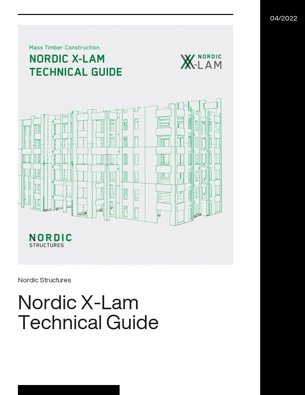
Nordic X-Lam Technical Guide

The Nordic X-Lam Technical Guide is a comprehensive technical resource for architects, engineers, and construction professionals designing with cross-laminated timber (CLT) systems from Nordic Structures. The guide provides essential information to support the effective specification and integration of Nordic X-Lam panels in mass timber buildings.

The document details panel properties, structural performance, and typical applications, with guidance on sizing, spans, loading conditions, and connections. It also addresses key design considerations including fire performance, acoustics, vibration, and building code compliance, helping project teams evaluate system suitability across a range of project types.

Developed as a practical design reference, the Nordic X-Lam Technical Guide supports coordinated, efficient project delivery by providing a clear technical framework for incorporating CLT systems into contemporary wood construction.

Unlocking Affordable Timber Innovations in Structure, Prefabrication, and Code
Browse Resources
Exposed Mass Timber Calculator
Federal Call for Proposals Opens Under $500M Forest Sector Transformation Investment
Limberlost Place: Video Case Study
Shearwalls – US Version
International Perspectives on Sustainable Housing Development
Building Success: The Nshwaasnangong Child Care and Family Centre Story
AtTEK – Fire Protection for Attic Applications
For new wood, remember: The wood must be dry.  Drying time depends on a few factors. Ideally the wood should be kiln-dried (stamped “S-DRY”, “KD” or “KDAT”, see...
Acrylic A type of water-borne coating product containing acrylic polymers. Alkyd A type of polyester resin. Term often used to signify solvent-borne coatings, e.g., oil...
Canada has had a wood preservation industry for about 100 years.  Canada is tied with the UK as the world’s second largest producer of treated wood (the USA is first...
FPInnovations has been field testing the performance of treated wood products for years. Click one of these categories for performance data from our field tests....
In the early 1900s, light-frame wood construction and heavy timber, up to ten-storeys in height, was commonplace in major cities throughout Canada. The longevity and...
What do the experts have to say about wood-frame mid-rise construction? Graham Finch, Building Science Research Engineer Michael Green, Principal, Michael Green Architecture...
On behalf of the Canadian Commission on Building and Fire Codes (CCBFC) the National Research Council (NRC) Codes Canada publishes national model codes documents that set out...
Supplementary treatment may be added wherever on-site cutting or drilling of wood is unavoidable, or where it is suspected the original protection measures may be inadequate....
Fasteners, Connectors and Flashing for Wood Treated With Copper-Based Preservatives The presence of moisture is a precondition for corrosion of metals. Treated wood is...
Treatability of Major North American Softwoods Some wood is easier to treat than others. The particular structure of the cells for a given piece of wood will determine how...
Individuals in the design and construction community are increasingly choosing materials, design techniques and construction procedures that improve a structure’s ability...
Since remedial treatment is intended to solve a known insect or decay problem, the first thing to do is investigate the extent of the problem and, if necessary, provide...

Get Access to Our Resources

Stay in the loop and don’t miss a thing!

1
2
3

Get Access to Our Resources

Stay in the loop and don’t miss a thing!

What’s Your Occupation?

Help us personalize the content for you.

What Interests You the Most?

Help us personalize the content for you.

Filters

Expertise Icon
Field of Expertise
Province Icon
Province
Member Type Icon
WoodWork National Partners

Filters

Post Type Icon
Post Type
Persona Icon
Persona
Language Icon
Language
Tags Icon
Tags
Mass Timber Plus Icon Environment Plus Icon Safety Plus Icon Durability Plus Icon Design Systems Plus Icon Budget Plus Icon Construction Management Plus Icon Fire Resistance Plus Icon Tall Buildings Plus Icon Short Buildings Plus Icon
Date Icon
Date
Line Separator